Edit Net
Other Related Resources
Parent page: PCB Dialogs
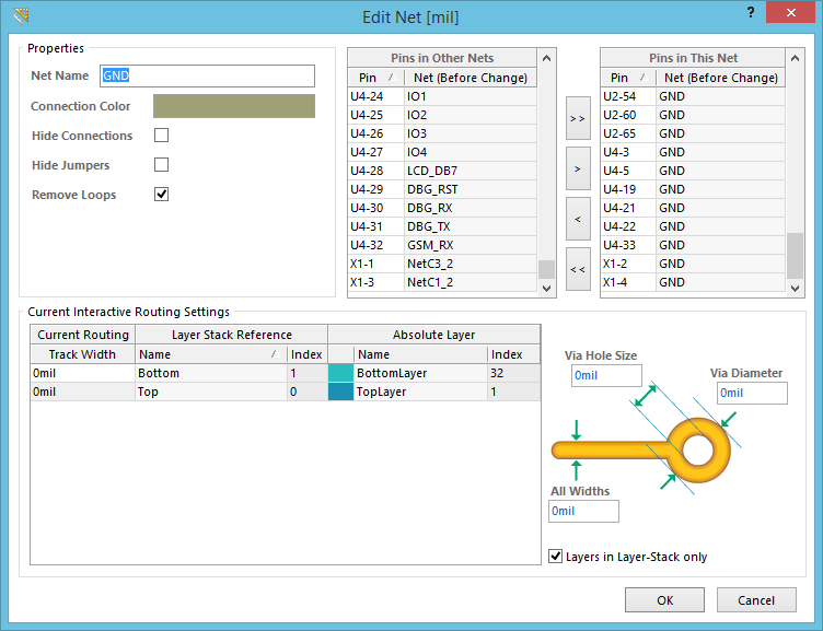
The Edit Net dialog
Summary
This dialog provides controls to browse the properties of the focused net, manage which pins (pads) of components in the design are part of the net, and also change the preferred routing widths and via sizes to use when interactively routing the net.
Access
The dialog is accessed from the PCB Editor in the following ways:
- Double-click on the desired net in the Nets region of the PCB panel (when configured in Nets mode).
- In the design workspace, right-click over an object in the desired net then choose Net Actions » Properties from the context menu.
- Double-click on the desired net (or select the net then click the Edit button) in the Netlist Manager dialog.
Options/Controls
Properties
- Net Name - the current name for the net. This can be changed as required.
- Connection Color - the current color used for the (unrouted) connection lines associated to this net. By default, all new nets are colored the same, with the color specified in the Default Color for New Nets field on the Board Layers And Colors tab of the View Configurations dialog. Click the color sample to change the color as required using the standard Choose Color dialog.
- Hide Connections - enable this option to hide all connection lines for the net.
- Hide Jumpers - enable this option to hide all jumpers displayed for components whose jumpered pins are members of this net.
- Remove Loops - this option controls whether redundant loop segments of routed track (and associated redundant vias) for this net are removed when re-routing to modify existing route paths. Disable this option to exclude the net from automatic loop removal.
Pin Management
The controls in this region provides controls to manage the pins (component pads) belonging to this net:
- Pins in Other Nets - this is a listing of all component pins (pads) that are not currently part of this net.
- Pins in This Net - this is a listing of all component pins (pads) that are currently part of this net.
 (Add All) - click this button to quickly transfer all pins from the Pins in Other Nets list to the Pins in This Net list.
- (Add Selected) - click this button to quickly transfer those pins currently selected in the Pins in Other Nets list to the Pins in This Net list.
- (Remove Selected) - click this button to quickly transfer those pins currently selected in the Pins in This Net list to the Pins in Other Nets list.
- (Remove All) - click this button to quickly transfer all pins from the Pins in This Net list to the Pins in Other Nets list.
Current Interactive Routing Settings
This region gets loaded with information when:
- You select a predefined favorite track width and/or via sizing when interactively routing the net. Choice is made using the Choose Width dialog (Shift+W) or Choose Via Size dialog (Shift+V). The predefined widths and sizes themselves are configured in the Favorite Interactive Routing Widths and Favorite Interactive Via Sizes dialogs.
- You set a specific track width and/or via sizing on-the-fly while interactively routing the net (press Tab to access the Interactive Routing dialog).
You also have the ability to change settings directly in the dialog.
- Track Width - this is a list of the available routing (signal) layers for the board and the current track width used when routing the net on a layer. When the User Choice feature is used and choose a favorite routing track width (Shift+W while interactively routing), that width will be loaded here. The same is true for a value specified on-the-fly while routing. If you chose to apply that width to all layers, the value will be loaded into this field for all layers. If not, only the entry for the layer on which the routing was being performed will get loaded with the value.
The track width for each layer can be modified directly, adjusting whatever has been previously loaded.
- Via Hole Size - the current via hole size used when dropping a via while routing this net. When the User Choice feature is used and you choose a favorite routing via size (Shift+V while interactively routing), the hole size portion of that choice will be loaded here. The same is true for a value specified on-the-fly while routing. The hole size can be modified directly, adjusting whatever has been previously loaded.
- Via Diameter - the current via diameter used when dropping a via while routing this net. When the User Choice feature is used and you choose a favorite routing via size (Shift+V while interactively routing), the diameter portion of that choice will be loaded here. The same is true for a value specified on-the-fly while routing. The diameter can be modified directly, adjusting whatever has been previously loaded.
- All Widths - if the User Choice feature is used and you chose to apply a predefined favorite/on-the-fly routing track width to all layers, the chosen/specified value will be loaded into this field. If the chosen/specified value was intended for the active routing layer only, then an entry of zero will appear in this field (and all Track Width fields for the other layers).
- Layers in Layer-Stack only - enable this option to have User Choice values loaded for layers in the layer stack only.