Board Layers and Colors
Contents
Parent page: PCB Dialogs
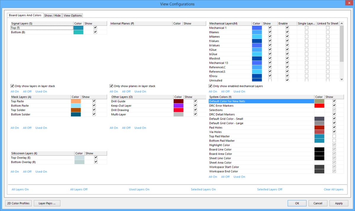
The Board Layers and Colors tab of the View Configurations dialog
Summary
This tab of the View Configurations dialog provides controls to configure the display of layers for the board and colors assigned to those layers.
Access
This is one of three tabs available for a 2D view configuration – accessed from within the View Configurations dialog. This dialog can be accessed from both the PCB Editor and the PCB Library Editor in the following ways:
- In 2D Layout Mode, click View | View |
 » View Configuration from the main menus.
 - Press the L key.
Options/Controls
Signal Layers
This region of the tab displays a list of signal layers for the board. Each layer in the list is presented in terms of:
- Signal Layers - the name of the layer. This field is not editable. For a layer that has an entry in brackets after its name (Top Layer, Bottom Layer and Mid-Layers 1-9), use that entry as a keyboard shortcut to quickly toggle that layer's visibility in the workspace (toggling its Show field).
- Color - displays the color currently assigned to the layer. To change it, click the color swatch then select a new color from the 2D System Colors dialog.
- Show - reflects the visibility of the layer in the workspace. Enabled (checked) means the layer will be visible in the workspace. Click to toggle as required.
The following additional option is available to manipulate the layers presented in the list:
- Only show layers in layer stack - enable this option to only work with used signal layers (those defined as part of the layer stack for the board) in the Layer Stack Manager dialog (Home | Board | ).
Internal Planes
This region of the tab displays a list of internal plane layers for the board. Each layer in the list is presented in terms of:
- Internal Planes - the name of the layer. This field is not editable.
- Color - displays the color currently assigned to the layer. To change it, click the color swatch then select a new color from the 2D System Colors dialog.
- Show - reflects the visibility of the layer in the workspace. Enabled (checked) means the layer will be visible in the workspace. Click to toggle as required.
The following additional option is available to manipulate the layers presented in the list:
- Only show planes in layer stack - enable this option to only work with used internal plane layers (those defined as part of the layer stack for the board) in the Layer Stack Manager dialog (Home | Board | ).
Mechanical Layers
This region of the tab displays a list of mechanical layers for the board. Each layer in the list is presented in terms of:
- Mechanical Layers - the name of the layer. The name can be changed from the default naming scheme (
Mechanical 1,Mechanical 2, etc.,) to a more meaningful name reflective of for what the layer is being used. To do so, click once on the name field to focus it then click again to edit. - Color - displays the color currently assigned to the layer. To change, click the color swatch then select a new color from the 2D System Colors dialog.
- Show - reflects the visibility of the layer in the workspace. Enabled (checked) means the layer will be visible in the workspace. Click to toggle as required. Note that the layer's Enable option must also be enabled before the layer will be visible in the workspace.
- Enable - reflects whether the layer is enabled as part of the PCB's layer set. A mechanical layer will only be available (visible) in the workspace as a tabbed layer if this option is enabled (and its Show option is also enabled). With this option enabled, it is considered to be 'in use' and part of the set of layers defined and stored as part of the PCB document. Toggle this option to enable/disable the layer as required. If the layer contains component primitives, you cannot disable the layer. If it contains non-component primitives, you can disable the layer; a confirmation dialog will appear asking whether you want to delete all primitives from the layer and remove it from the set of layers.
- Single Layer Mode - enable this option to be able to display design objects on the layer when viewing in single layer mode. This option works in conjunction with the Single Layer Mode option on the View Options tab of the dialog.
- Linked To Sheet - enable this option for the layer to be linked to the PCB sheet. By placing objects on mechanical layers then linking those layers to the sheet, you can create your own drawing templates that can be displayed or hidden as required, such as a border, grid reference, and title block.
The following additional option is available to manipulate the layers presented in the list:
- Only show enabled mechanical layers - enable this option to only list and work with enabled mechanical layers.
Mask Layers
This region of the tab displays a list of mask layers (solder and paste) for the board. Each layer in the list is presented in terms of:
- Mask Layers - the name of the layer. This field is not editable.
- Color - displays the color currently assigned to the layer. To change it, click the color swatch then select a new color from the 2D System Colors dialog.
- Show - reflects the visibility of the layer in the workspace. Enabled (checked) means the layer will be visible in the workspace. Click to toggle as required.
Other Layers
This region of the tab displays a listing of the following layers for the board: Drill Guide, Keep-Out Layer, Drill Drawing and Multi-Layer. Each layer in the list is presented in terms of:
- Layer Name - the name of the layer. This field is not editable.
- Color - displays the color currently assigned to the layer. To change, click the color swatch then select a new color from the 2D System Colors dialog.
- Show - reflects the visibility of the layer in the workspace. Enabled (checked) means the layer will be visible in the workspace. Click to toggle as required.
Silkscreen Layers
This region of the tab displays a list of the silkscreen layers for the board. Each layer in the list is presented in terms of:
- Silkscreen Layers - the name of the layer. This field is not editable. Use the entry in brackets after its name as a keyboard shortcut to quickly toggle that layer's visibility in the workspace (toggling its Show field).
- Color - displays the color currently assigned to the layer. To change it, click the color swatch then select a new color from the 2D System Colors dialog.
- Show - reflects the visibility of the layer in the workspace. Enabled (checked) means the layer will be visible in the workspace. Click to toggle as required.
System Colors
This region of the tab displays a list of the special, layer-independent system items that can be displayed on a PCB document. Each entry in the list is presented in terms of:
- System Colors - the name of the special system item. This field is not editable.
- Color - displays the color currently assigned to the item. To change it, click the color swatch then select a new color from the 2D System Colors dialog.
- Show - reflects the visibility of the item in the workspace. Enabled (checked) means the item will be visible in the workspace. Click to toggle as required.
Additional Controls
The following sections describe additional controls available that apply to a specific region of the tab, all regions of the tab, or are available on the tab's right-click menu.
Region-Specific
- All On - click this control to make all layers/items in the current list visible in the workspace (Show option enabled). Note that for mechanical layers, this control does not enable the layers. You must also enable a mechanical layer in order to make it visible in the workspace.
- All Off - click this control to make all layers/items in the current list hidden from the workspace (Show option disabled).
- Used On - click this control to make only those layers/items in the current list that are in use (for example, a layer that has one or more design primitives placed on it) visible in the workspace (Show option enabled). All other layers/items currently not in use will be hidden from the workspace (Show option disabled).
Global
- All Layers On - click this control to make all layers/items across all current lists visible in the workspace (Show option enabled). Note that for mechanical layers, this control does not enable the layers. You must also enable a mechanical layer in order to make it visible in the workspace.
- All Layers Off - click this control to make all layers/items across all current lists hidden from the workspace (Show option disabled).
- Used Layers On - click this control to make only those layers/items across all current lists that are in use (for example, a layer that has one or more design primitives placed on it) visible in the workspace (Show option enabled). All other layers/items currently not in use will be hidden from the workspace (Show option disabled).
- Selected Layers On - click this control to make selected layers/items across all current lists visible in the workspace (Show option enabled). Note that for mechanical layers, this control does not enable the layers. You must also enable a mechanical layer in order to make it visible in the workspace.
- Selected Layers Off - click this control to make selected layers/items across all current lists hidden from the workspace (Show option disabled).
- Clear All Layers - click this control to deselect all currently selected layers/items across all current lists in the tab.
Right-click Menu
- Change Color - use this command to access the 2D System Colors dialog to change the color for the currently focused layer/item.
- Show/Hide - use this command to toggle the visibility (Show option) for the currently focused layer/item.
- Default Color Scheme - use this command to quickly change assigned layer/item colors, across all regions of the tab, to those defined in the Default color profile (Default.PCBSysColors).
- Classic Color Scheme - use this command to quickly change assigned layer/item colors, across all regions of the tab, to those defined in the Classic color profile (Classic.PCBSysColors).