Interactive Routing
Contents
Parent page: Commands

A board being interactively routed; the Ctrl+click shortcut is used to complete many of the connections.
Summary
Routing is the process of connecting the nodes in each net by placing a series of track segments and vias to define a path from one node to the next. CircuitStudio includes a sophisticated interactive routing engine that greatly enhances your routing efficiency. Capabilities include:
- A number of routing modes, such as stop at first obstacle, walkaround, and push and shove
- Powerful dragging capabilities that maintain track angles and orthogonality
- A loop removal feature that makes re-routing a quick and easy process
Details
Routing commands, unroute commands, and commands to control the display of the connection lines (ratsnest) are clustered in the Home | Routing group on the Ribbon.
The Route button has 2 functions: the upper half always launches the Interactive Routing commmand; the lower half is used to access the routing menu, where you can select if you are routing one net, a differential pair, or multiple nets.
Summary of Commands
| Command | Behavior |
|---|---|
| Interactive Routing | Click the upper half of the Route button or select Interactive Routing from the menu, then click on a connection line or pad to begin routing that net. The command can also be accessed via the workspace right-click menu. |
| Differential Pair Routing | Route a differential pair. Click on either net in the pair to begin routing. Nets are configured as a differential pair in the Differential Pair Editor mode of the PCB panel. |
| Interactive Mutli-Routing | Route multiple nets simultaneously. |
| Unroute All | Remove all signal layer track segments and vias that have a net name on the entire board. Track segments and vias that are locked will not be removed. |
| Unroute Net | Remove all signal layer track segments and vias that have the net name of the net that you click on after selecting the command. Track segments and vias that are locked will not be removed. |
| Unroute Connection | Remove the signal layer track segments and vias that have the net name of the net that you click on after selecting the command up to the first pad in both directions. Track segments and vias that are locked will not be removed. |
| Unroute Component | Starting at the pads in the component that is clicked on, remove all touching signal layer track segments and vias until another component is reached. |
| Show All | Show all connection lines (ratsnest) on the entire board. |
| Show Net | Show the connection lines (ratsnest) for the chosen net. |
| Hide All | Hide all connection lines (ratsnest) on the entire board. |
| Hide Net | Hide the connection lines (ratsnest) for the chosen net. |
Interactive Routing Preferences
Routing preferences are configured in the PCB - Interactive Routing page of the Preferences dialog.
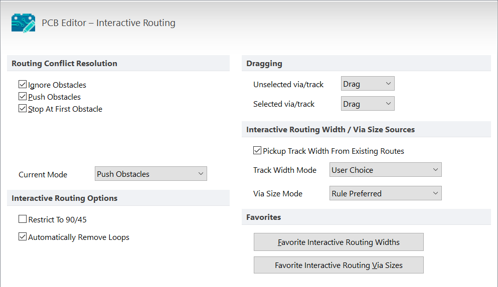
Configure the Interactive Routing options to suit your preferences. Press F1 over the dialog for more information about an option.
Interactive Routing Shortcuts
By its very nature, Interactive Routing is a process where the designer is busy interacting with their PC by moving the mouse and clicking to define vertices (corners). Because of this, the Interactive Router makes extensive use of shortcut keys, which are an essential ingredient to efficent routing.
| Shortcut Key(s) | Behavior |
|---|---|
| Shift+F1 or ~ (tilde) | Pop up a menu of interactive shortcuts; most settings can be changed on the fly by pressing the appropriate shortcut or selecting from the menu. |
| * or Ctrl+Shift+WheelRoll | Switch to the next available signal layer. A via is automatically added, in accordance with the applicable Routing Via Style design rule. |
| Shift+R | Cycle through the enabled conflict resolution modes. Enable the required modes in the PCB Editor - Interactive Routing preferences page. The current mode is shown on the Status bar. |
| Shift+S | Toggle single layer mode on and off . This is ideal when there are many objects on multiple layers. |
| Spacebar | Toggle the current corner direction. |
| Shift+Spacebar | Cycle through the various track corner modes. The styles are: any angle, 45°, 45° with arc, 90°, and 90° with arc. There is an option to limit this to 45° and 90° on the PCB Editor - Interactive Routing preferences page. |
| Ctrl+Left-Click | Auto-complete the connection being routed. Auto-complete will not succeed if there are un-resolvable conflicts with obstacles. |
| Ctrl | Temporarily suspend the Hotspot Snap, or press Shift + E to cycle through the three available modes (off / on for current layer / on for all layers). The current Hotspot Snap mode is shown on the Status bar. |
| End | Redraw the screen. |
| PgUp / PgDn | Zoom in / out, centered around the current cursor position. Alternatively, use the standard Windows mouse wheel zoom and pan shortcuts. |
| Backspace | Remove the last-committed track segment. |
| Right-click or ESC | Drop the current connection and remain in Interactive Routing mode. |
| 3 | Cycle the Track Width Source. The width can be: User Choice, Rule Minimum, Rule Preferred, or Rule Maximum. The current source is shown on the Status bar. |
| 5 | Toggle Follow Mouse Trail mode on/off. When this is off and routing in Walkaround, the shortest route path is found from the last click point to the current cursor location. When this is on and routing in Walkaround, the route path follows where you have moved the cursor. |
| Ctrl+Shift+G | Cycle the glossing strength. Glossing is where the software attempts to remove unnecessary wiggles and corners, resulting in cleaner and shorter routes. The current glossing strength is shown on the Status bar. |
Modifying Existing Routing
Rather than deleting or unrouting an existing route, CircuitStudio includes two approaches for modifying existing routing: re-arrange it or re-route it.
Re-arrange an Existing Route
- To interactively slide or drag track segments across the board, click, hold and drag, as shown in the animation below.
- The PCB editor will automatically maintain the 45/90 degree angles with connected segments, shortening and lengthening them as required.
Reroute an Existing Route
- There is no need to un-route a connection to redefine its path; click the Route button and start routing the new path.
- The Loop Removal feature will automatically remove any redundant track segments (and vias) as soon as you close the loop and right-click to indicate you are complete.
- You can start and end the new route path at any point, swapping layers as required.
- You can also create temporary violations by switching to Ignore Obstacle mode (as shown in the animation below), which you later resolve.
Some of the existing routing is being re-arranged, then two nets are re-routed. The Shift+R shortcut is used to cycle the routing mode and allow the temporary violation.