
Favorite Interactive Via Sizes
Parent page: PCB Dialogs
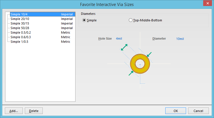
The Favorite Interactive Via Sizes dialog
Summary
This dialog provides controls to predefine your favorite via size to use when interactively routing a board using the Interactive Router.
Access
The dialog is accessed from the PCB Editor in the following ways:
- Click the Favorite Interactive Routing Via Sizes button on the PCB Editor - Interactive Routing page of the Preferences dialog.
- Click the Favorite Interactive Routing Via Sizes button in the Interactive Routing dialog, which is accessed while interactively routing by pressing the Tab key.
Options/Controls
- Via Sizes List - the left-hand region of the dialog lists all currently defined favorite via sizes (the default set are shown in the image at the top of this page). Each entry consists of a name and the system units used at the time the size was created and defined. The name reflects the Diameters mode; either Simple or T-M-B (for Top-Middle-Bottom), and the defined values for Diameter(s) and Hole Size. The possible name formats are:
- Simple <Diameter>/<HoleSize>
- T-M-B <TopLayerDiameter>-<MiddleLayerDiameter>-<BottomLayerDiameter>/<HoleSize>
Click on an entry in the list to access controls for editing its Diameter(s) and Hole Size.
- Via Size Definition - the right-hand region of the dialog presents the following controls for defining the size of the via currently selected in the left-hand region:
- Diameters - use this field to choose the Diameters mode, either Simple (the via diameter is the same for all routing layers), or Top-Middle-Bottom (the via diameter can be different for the Top Layer, all internal signal layers, and Bottom Layer).
- Hole Size - use this field to specify the size of the hole in the via.
- Diameter - if the Diameters mode is set to Simple, use this single field to define the diameter of the via. If the Diameters mode is set to Top-Middle-Bottom, use the available fields to define the diameter of the via on the Top Layer, Middle Layer and Bottom Layer.
- Add - click this button to add a new routing via size to the list. Use the controls on the right-hand side of the dialog to define the constraints of that size as required.
- Delete - click this button to delete the currently selected via size from the list.
Using Favorite Via Sizes
An incarnation of the Favorite Interactive Via Sizes dialog is accessed when you want to change the current routing via style to one of the predefined favorites. Press Shift+V while interactively routing to access the Choose Via Sizes dialog.
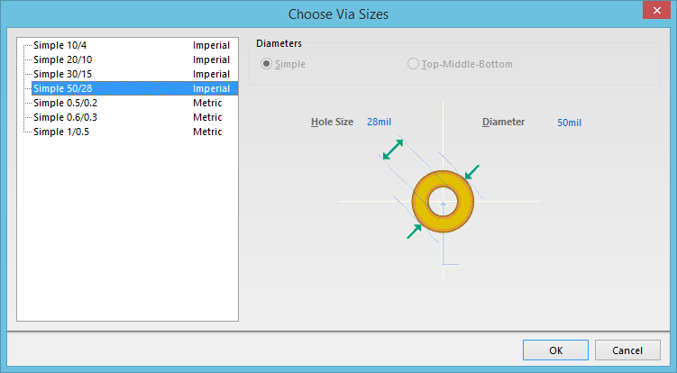
The Choose Via Sizes variation of the Favorite Interactive Via Sizes dialog
Select an entry then click OK to switch to using that routing via style (in accordance with the boundaries of the applicable min-max Routing Via Style rule).