
PCB Printout Properties
Contents
Parent page: WorkspaceManager Dialogs
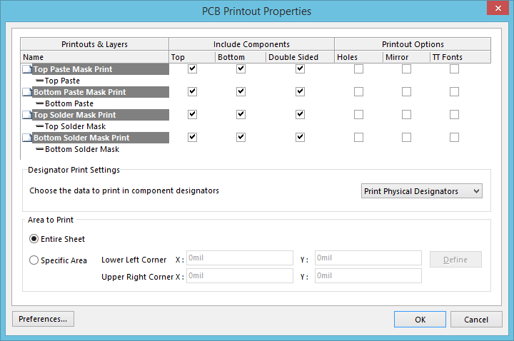
The PCB Printout Properties dialog
Summary
This dialog provides controls to define and manage the printout(s) required for the specific print-based documentation that is to be generated from the board.
Access
The dialog is accessed in the following ways:
- By clicking the Advanced button in the associated Print Properties dialog for the document type (accessed using the relevant Page Setup control).
- Right-clicking in the Print Preview dialog then choosing the Configuration command from the context menu.
- With the entry for a PCB-supported printout type selected (with the exception of PCB 3D Prints) on the Default Prints tab of the Project Options dialog, click the Configure button.
Options/Controls
Main Grid
This region presents the configured printouts in a grid. The grid is comprised of three columns:
- Printouts & Layers - this column lists the currently defined printouts and their constituent layers. The following printout-based entities are supported:
- Printout - a standard printout, manually configured with requisite layers.
- Drill Printout Set - comprised of a set of printouts generated for each existing drill-pair, with drill layers determined by the Layer Stack. Each printout will comprise of the drill layer (Drill Drawing or Drill Guide) as nominated for the set.
- Include Components - this column enables you to control which components are included in an associated printout/printout set; either those on the top, those on the bottom, or components on both sides.
- Printout Options - this column enables you to control additional options with respect to an associated printout/printout set; whether or not to show holes, mirror layers, and enable font substitution.
The following list of commands are available from the right-click menu accessed from anywhere within the dialog:
- Create Final - use this command to quickly create a complete, predefined final artwork print-set for the source PCB document.
- Create Composite - use this command to quickly create a predefined multi-layer composite print for the source PCB document.
- Create Power-Plane Set - use this command to quickly create predefined power-plane drawings for the source PCB document.
- Create Mask Set - use this command to quickly create predefined solder/paste mask drawings for the source PCB document.
- Create Drill Drawings - use this command to quickly create a predefined set of drill drawings and guides for the source PCB document.
- Create Assembly Drawings - use this command to quickly create predefined assembly drawings for the source PCB document.
- Create Composite Drill Guide - use this command to quickly create a predefined composite drill drawing for the source PCB document.
- Insert Printout - use this command to insert a new standard printout for the print-based output currently being configured. The printout will be added immediately above the currently focused printout/printout set.
- Insert Drill Printout Set - use this command to insert a new drill printout set for the print-based output currently being configured. The drill printout set will be added immediately above the currently focused printout/printout set.
- Insert Layer - use this command to insert a new layer into the focused printout/printout set. The Layer Properties dialog will appear, from where you can choose from a list of all used layers for the board. The layer will be added immediately above the focused entry within that printout/printout set.
- Move Up - use this command to move the focused entry upward within a printout/printout set, or move the focused printout/printout set upward within the overall print set.
- Move Down - use this command to move the focused entry downward within a printout/printout set, or move the focused printout/printout set downward within the overall print set.
- Delete - use this command to remove the selected entry(ies) from the associated parent printout/printout set, or the selected printout(s)/printout set(s) from the overall print-set currently being configured. You will be prompted for confirmation of the deletion.
- Properties - use this command to access either the Layer Properties dialog, the Iterated Layer Properties dialog, the Printout Properties dialog, or the Drill Printout Properties dialog, depending on whether the focused entry is a layer, an iterated layer, a printout, or a drill printout set, respectively.
- Preferences - use this command to access the PCB Print Preferences dialog, from where you can define global options that apply to all print sets.
Designator Print Settings
Use the control in this region of the dialog to specify the type of designator information to be included on the printouts. Opt to either Print Phyiscal Designators, or Print Logical Designators.
Area to Print
Use the controls in this region of the dialog to determine the area of the board to be printed. Choose from:
- Entire Sheet - print the whole board.
- Specific Area - only print the defined area. With this option enabled, the following controls become available:
- Lower Left Corner X/Y - use these fields to define the X and Y coordinates for the bottom-left corner of the required print area.
- Upper Right Corner X/Y - use these fields to define the X and Y coordinates for the top-right corner of the required print area.
- Define - click this button to define the required print area directly in the workspace. You will be taken into the workspace in which you can click to define the two diagonally-opposite corners of the area. The coordinates of your chosen locations will be filled into the respective fields, back in the PCB Printout Properties dialog.
Additional Buttons
- Preferences - click this button to access the PCB Print Preferences dialog. Use this dialog to define printout-related preferences including the coloring for each layer that can be printed, whether any mechanical layers are included in a printout automatically, and font substitution.