Engineering Change Order
Parent page: WorkspaceManager Dialogs
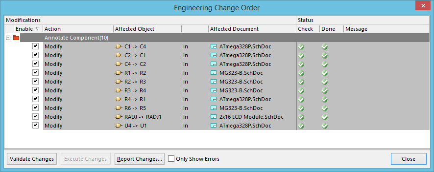
The Engineering Change Order dialog
Summary
This dialog presents the currently generated Engineering Change Order (ECO). An ECO lists all modifications required to implement changes to one or more design documents in order to bring those documents into a state of synchronization.
Access
ECOs are used to effect design updates in a variety of situations. The ways in which the dialog can be accessed include the following:
- Click the Create Engineering Change Order button in the Differences between dialog.
- Click the Accept Changes (Create ECO) button in the Annotate dialog when performing annotation on the source schematic documents.
The Schematic and PCB Editors also provide direct synchronization commands. These commands are direct in the sense that the update direction for any differences is fully one way or the other. The Differences between dialog will not open. Instead, where differences are detected, the Engineering Change Order dialog will be presented directly – loaded with the modifications needed to push the design changes from the schematic to the PCB or vice-versa.
The following direct synchronization commands are available from within the target PCB document:
- Home | Project | Project » Update Schematics - this command is used to update the parent project's source schematics with changes made to the PCB design.
- Home | Project | Project » Import Changes From - this command is used to update the active PCB document with changes made to the source schematic documents of the parent project.
The following direct synchronization command is available from within a source schematic document:
- Home | Project | Project » Update PCB Document - this command is used to update the indicated PCB document with changes made to the project's source schematic documents.
Options/Controls
The dialog is essentially divided into two main regions - Modifications and Status.
Modifications
This region of the dialog lists all modifications necessary to implement the changes required to bring about synchronization. Modifications are grouped by modification type as listed, and enabled on the ECO Generation tab of the Project Options dialog. The entry at this group level reflects the number of modifications of that type. Each specific modification in this region is listed in terms of the following:
- Enable - this option determines whether or not the modification will be included when the ECO is executed. Click directly on the checkbox to toggle its state between enabled/included (checkbox checked) and disabled/excluded (checkbox unchecked).
- Action - the specific action to be carried out. The types of actions are dependent on what type of ECO needs to be done and can include Add, Remove, and Modify.
- Affected Object - the object affected by the action.
- Affected Document - the document upon which the action will be carried out.
By default, all modifications are enabled for inclusion when the ECO is executed. Enable/disable each modification entry as required, individually or use the following commands available from the right-click menu to change the enabled state of multiple modifications:
- Enable All - use this command to enable all modifications.
- Disable All - use this command to disable all modifications.
- Enable Selected - use this command to enable all selected modifications.
- Disable Selected - use this command to disable all selected modifications.
- Enable all of same Kind - use this command to enable all modifications of the same modification type as the currently focused modification.
- Disable all of same Kind - use this command to disable all modifications of the same modification type as the currently focused modification.
Multiple modifications can be selected in the list using standard multi-select techniques (Ctrl+click, Shift+click). In addition, the right-click menu provides an Invert Selection command to quickly select all modifications not currently selected in the list and deselect those that are.
Status
This region of the dialog presents the following status information for each enabled modification:
- Check - this field shows the result of running a validation check on the modification. A green check (
 ) means that the proposed change is supported and will be carried out upon execution of the ECO. A red cross () means that the proposed change is invalid and will not be carried out when the ECO is executed.
 - Done - this field shows the result of execution of the modification. A green check () means that the valid modification executed successfully.
- Message - if the modification fails the validation stage, an entry will appear in this field (and also in the Messages panel) giving an indication as to why it failed.
Additional Controls
The following buttons are available at the bottom of the dialog:
- Validate Changes - click this button to run a validation check on the modifications enabled for inclusion in the ECO. Validation results will appear in the Check column in the Status region of the dialog.
- Execute Changes - click this button to execute the ECO and effect the valid changes contained therein. Execution results will appear in the Done column in the Status region of the dialog. Remember, only changes that pass the validation stage will be executed.
- Report Changes - click this button to generate a report for the modifications contained in the ECO. The report will be loaded into the Report Preview dialog. Use this dialog to browse the report before ultimately exporting it to one of various supported formats or printing it directly.
- Only Show Errors - enable this option to only show Engineering Change Order errors; validated changes will not be displayed. Showing the list of errors only will enable you to quickly review and make necessary changes to your design so that the resulting ECO validates completely, and therefore, you have success when the ECO is executed.