
PCB Rules And Constraints Editor
Contents
Parent page: PCB Dialogs
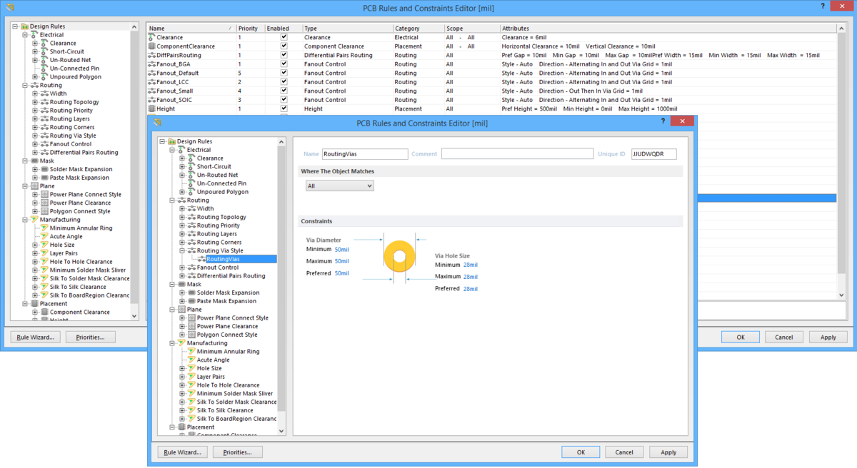
The PCB Rules and Constraints Editor dialog
Summary
The PCB Rules and constraints Editor dialog provides controls to browse and manage the defined design rules for the current PCB document. Design rules collectively form an instruction set for the PCB Editor to follow. Each rule represents a requirement of your design and many of the rules, for example, clearance and width constraints, can be monitored as you work with the online Design Rule Checker (DRC). Certain rules are monitored when using additional features of the software, for example, routing-based rules when using the Situs Autorouter to route a design.
Access
The dialog is accessed from the PCB Editor by clicking Home | Design Rules | ![]() from the main menus.
from the main menus.
Options/Controls
The dialog includes a static pane on the left and a main editing region on the right that changes in context with the selection on the left.
Left-Hand Pane
In the folder-tree pane on the left side of the dialog, each of the supported design rule categories, and types thereof, are listed under the Design Rules folder. The following rule categories and types are supported:
- Electrical - this category offers the following rule types: Clearance, Short-Circuit, Un-Routed Net, Un-Connected Pin, and Unpoured Polygon.
- Routing - this category offers the following rule types: Width, Routing Topology, Routing Priority, Routing Layers, Routing Corners, Routing Via Style, Fanout Control, and Differential Pairs Routing.
- Mask - this category offers the following rule types: Solder Mask Expansion, and Paste Mask Expansion.
- Plane - this category offers the following rule types: Power Plane Connect Style, Power Plane Clearance, and Polygon Connect Style.
- Manufacturing - this category offers the following rule types: Minimum Annular Ring, Acute Angle, Hole Size, Layer Pairs, Hole To Hole Clearance, Minimum Solder Mask Sliver, Silk To Solder Mask Clearance, Silk To Silk Clearance, and Silk To BoardRegion Clearance.
- Placement - this category offers the following rule types: Component Clearance and Height.
Click on the root folder to access a summary listing in the main editing region of the dialog of all specific rules that have been defined for all design rule types across all categories.
Click on a category folder to access a summary listing of all specific rules that have been defined for all associated design rule types of that category.
Click on a rule type folder to access a summary listing of all specific rules that have been defined for that type.
Click on the entry for a specific rule in the folder-tree pane (or double-click on its entry in a summary list) to access controls for managing its definition.
Right-Click Menu
The following commands are available from the right-click context menu for the pane:
- New Rule - use this command to create a new rule of the currently selected rule type. The new rule will be added to the folder-tree and will also appear in the summary list for that rule type. The rule name will appear bold to distinguish it as being new and yet to be 'applied'.
- Duplicate Rule - use this command to quickly create an identical copy of the currently selected existing rule. The duplicate rule will be named the same as the original with the addition of a suffix (e.g., _1) to distinguish it. Its definition (scope, constraints, etc.,) will be identical to that of the original.
- Delete Rule - use this command to delete the specific rule that is currently selected in the folder-tree. The rule name will appear bold with strike-through highlighting to distinguish it as being a deletion that is yet to be 'applied'.
- Report - use this command to generate a report of currently defined design rules. The report can cater for all rule categories, a specific rule category, or a specific rule type depending on the selected entry in the folder-tree. The Report Preview dialog will open with the appropriate report already loaded. Use this dialog to inspect the report using various page/zoom controls before ultimately exporting it to file or printing it.
- Export Rules - use this command to export your favorite rule definitions to file. The Choose Design Rule Type dialog will open. Select the rule types you want to export then click OK. The Export Rules to File dialog will open from where you can determine where and under what name the exported rules file (*.rul) is to be stored.
- Import Rules - use this command to import rule definitions from a previously save PCB Rule file. The Choose Design Rule Type dialog will open. Select the rule types you want to import then click OK. The Import File dialog will open from where you can browse to and open the particular PCB Rule file (*.rul) you want to import.
Main Editing Region
This region of the dialog changes in accordance with what is currently selected in the left-hand pane. It presents two different views:
- Summary Listing - if the root Design Rules folder or any of the child rule category or type folders are clicked in the left-hand pane, this region will present a summary listing of all defined rules or all rules of the selected category or type. Each rule is listed in terms of the following:
- Name - the name of the rule.
- Priority - the rule's current priority.
- Enabled - whether the rule is currently enabled or disabled (click to toggle this state).
- Type - the type of rule.
- Category - the rule category to which it belongs.
- Scope - the scope of the rule (i.e. what object(s) it applies to).
- Attributes - the constraint attributes that have been defined for the rule.
The summary listings also provide the following buttons to act on selected entries in the currently displayed listing:
- New Rule - click to create a new rule of the type currently selected in the folder-tree pane of the dialog.
- Delete Rule(s) - click to delete the specific rule or rules currently selected in the displayed list. A deleted rule's name will appear bold with strike-through highlighting to distinguish it as being a deletion that is yet to be 'applied'.
- Duplicate Rule - click to quickly create an identical copy of the currently selected existing rule in the displayed list.
- Report - click to generate a report containing all design rules in the currently displayed list. The Report Preview dialog will open with the report already loaded. Use this dialog to inspect the report using various page/zoom controls before ultimately exporting it to file or printing it.
- Rule Definition - when a specific rule is selected in the left-hand pane, this region will present the following controls for defining that rule.
- Name - the current name of the rule. This can be changed as required.
- Comment - this field displays any comment added for the rule, for example, a meaningful description for what the rule is being used.
- Unique ID - the unique identifier for the rule. Every rule is itself a design object and is, therefore, a tangible piece of data. The use of an ID ensures uniqueness. Where the Unique ID really comes into play, however, is for a rule that has been created within the schematic domain. When adding design rule parameters to objects on a schematic, a unique ID is given to each rule parameter. The same IDs are given to the corresponding design rules that are created in the PCB. With this Unique ID, the constraints of a rule can be edited on either the schematic or PCB side, and the changes pushed through upon synchronization.
- Rule Scoping Controls - this region provides controls for determining the scope of the rule in terms of the objects to which it applies or between. See the section Rule Scoping Controls for more detail on using the controls in this region.
- Constraints - this region of the dialog presents the constraints applicable to the type of rule being edited. Use the various controls to configure these constraints as required.
Rule Scoping Controls
When defining the scope of a design rule - the extent of its application - you are essentially defining the member objects that are governed by the rule. Use the options available to set the scope as required. Depending on whether the rule is unary or binary, you will need to define one or two scopes.
Controls are identical whether defining one or two rule scopes and are detailed in the following sections.
Where The Object Matches
- Scoping Option - choose one of the following scoping options:
- All - choose this option to generate a scope that targets all design objects.
- Net - choose this option to generate a scope that targets all objects in a specific net.
- Layer - choose this option to generate a scope that targets all objects on a specific layer. Choose the required layer from the top drop-down field.
- Net and Layer - choose this option to generate a scope that targets all objects in a specific net and on a specific layer. Choose the required net from the top drop-down field and the required layer from the bottom drop-down field.
- Top Drop-Down Field - when using the Net (or Net and Layer) or Layer options, this field's drop-down will populate with all defined nets in the design or all currently enabled layers in the design. Choose the required target accordingly.
- Bottom Drop-Down Field - when using the Net and Layer option, this field's drop-down will populate with all currently enabled layers in the design. Choose the required layer accordingly.
Additional Buttons
The following additional controls are provided at the bottom-left of the dialog:
- Rule Wizard - click this button to run the Design Rule Wizard, which steps you through the process of creating a new design rule.
- Priorities - click this button to access the Edit Rule Priorities dialog, from where you can manage the priorities of multiple rules of the same rule type.