
PCB Editor - DRC Violations Display
Contents
Parent page: PCB Preferences
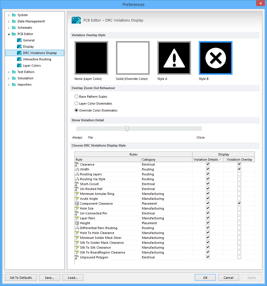
The PCB Editor - DRC Violations Display page of the Preferences dialog
Summary
The PCB Editor – DRC Violations Display page of the Preferences dialog provides a range of controls that determine the visual functionality of the DRC Violations Display feature within the PCB workspace.
Access
The PCB Editor – DRC Violations Display page is part of the main Preferences dialog (File | ![]() ) and is accessed by clicking the DRC Violations Display entry under the PCB Editor folder in the left hand pane of the dialog.
) and is accessed by clicking the DRC Violations Display entry under the PCB Editor folder in the left hand pane of the dialog.
Options/Controls
Violation Overlay Style
Select the visual overlay style to specify how violations appear in the PCB workspace. Choose from the following options:
- None (Layer Color) - the DRC override color is ignored, leaving only the default layer color visible.
- Solid (Override Color) - the DRC override color is used, totally overriding the default layer color.
- Style A - the DRC override color is used in the display of an exclamation-type pattern, leaving the default layer color also visible.
- Style B - the DRC override color is used in the display of a cross-type pattern, leaving the default layer color also visible.
Overlay Zoom Out Behavior
Use these options to determine how the overlays are displayed when you zoom out:
- Base Pattern Scales - select to scale the base pattern as you zoom out.
- Layer Color Dominates - select to have the assigned layer color become more dominant the further you zoom out until the color is not noticeable.
- Override Color Dominates - select to have the assigned net override color become more dominant the further you zoom out until the color is not noticeable.
Show Violation Detail
This option determines the zoom point at which the custom violation graphics for a violated design rule will be displayed. Setting the slider bar more towards Close will result in the violation details appearing when you are more 'zoomed in'. Conversely, to keep the details visible while zooming out to a greater extent, set the slider bar more towards Far. To keep the violation details displayed regardless of zoom level, set the slider bar to Always.
Choose DRC Violations Display Style
This region presents a grid allowing you to choose the display style used on a per-rule basis.
- Enabling the Violation Details field for a rule type will use the associated custom violation graphics to display the DRC violations of that rule.
- Enabling the Violation Overlay field will display the violations using the specified overlay style.
Right-click anywhere in the region to access a context menu, with commands to quickly enable or disable use of a violation display type for all rule types. You can also quickly enable the display of violations – detailed graphics or overlay styles – for only those rules currently being used in the design.