Schematic Editing Strategies
Contents
- Grids and Cursors
- Types of Grids
- Where the Grid Values are Defined
- Pre-configuring Available Grid Values
- Working with the Grids
- Choosing Your Preferred Cursor
- Placing Design Objects
- Morphing an Object
- Wiring the Schematic
- Wire/Bus Placement Modes
- Junctions
- Editing Design Objects
- Graphically Editing Placed Objects
- Modifying the Wiring
- Breaking a Wire
- Moving or Dragging Schematic Objects
- Tips for Moving or Dragging Objects
- Multi-Wire Dragging
- Locking Objects from Moving
- Copy and Paste
- On-sheet Text Editing
- Annotation and Re-Annotation
- Non-Graphical Editing
- Editing Objects in the SCH Inspector Panel
Parent page: Exploring CircuitStudio
If you are just getting started in the schematic editor, this document will give you tips and pointers about how to place and edit design objects.
Grids and Cursors
Before you start placing objects in the schematic editor, you should know how to configure and use the grids, and set the cursor style.
Types of Grids
The schematic editor has three types of grids:
| Grid | Summary | Detail |
|---|---|---|
| Visible Grid | For visual presentation | This is the grid you see on the schematic sheet. The Visible grid appears whenever the zoom level allows it to be sufficiently spaced so it can be displayed as either lines or dots. The color of the visible grid and the choice of lines or dots is made in the Schematic - Grids page of the Preferences dialog. Note that the cursor is not locked to this grid. |
| Snap Grid | For the accurate placement of objects | The Snap grid is the grid to which the cursor is locked when placing or moving schematic design objects. It is important to select a Snap grid that suits both your company requirements and also the components used in your designs. The default Snap grid is in mils, and all Altium components are designed with their pins on a 100mil grid. |
| Electrical Grid | To simplify the creation of connections | The Electrical grid overrides the Snap grid to pull the cursor to the nearest electrical hotspot (such as the end of a pin) when the cursor is within the range of the current Electrical grid. |
Where the Grid Values are Defined
Set the grid values in the Document Options dialog (Project | Content | Document Options) or double click in the sheet border to open the dialog. Grid settings are saved with the individual design file, so grid settings may differ between design documents.
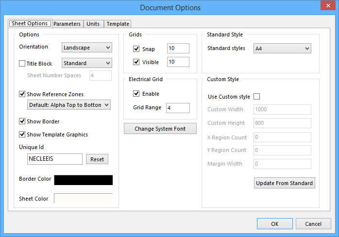
Grids are configured for each schematic sheet.
Pre-configuring Available Grid Values
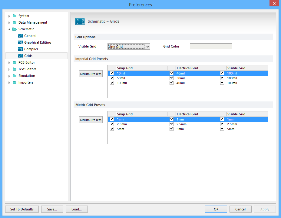
While the current grid values are saved with each document, you can also define a number different grids that you want to have available as you work. These pre-configured grids, also known as Grid Presets, are defined on the Schematic - Grids page of the Preferences dialog. It is these Snap Grid and Electrical Grid values that you cycle through when you press the G shortcut key to change the grid value as you work. Note that these settings are stored as environment settings, i.e. they stay with this installation of the software.
This preferences page is also where you select the Visible Grid style (lines or dots) and the Visible Grid Color.
Working with the Grids
In the video below, you can see the cursor behavior with the Snap grid set to 10. It is then cycled to 1 by pressing the G key once. Note how the Electrical grid becomes dominant and pulls the cursor to the end of the pin (the Electrical grid settings have been configured to 80mils for the video). As the wire is being placed, the Snap grid is cycled back to 10 by pressing G twice.
To help easily place objects that are not sensitive to the grid, such as strings, press the Ctrl key to temporarily change the grid to 1, as shown at the end of the video when the designator string is moved.

Press G to cycle through the preset grids. Note the Electrical grid pulling the cursor to the end of the pin. Ctrl is used to temporarily inhibit the Snap grid.
Choosing Your Preferred Cursor
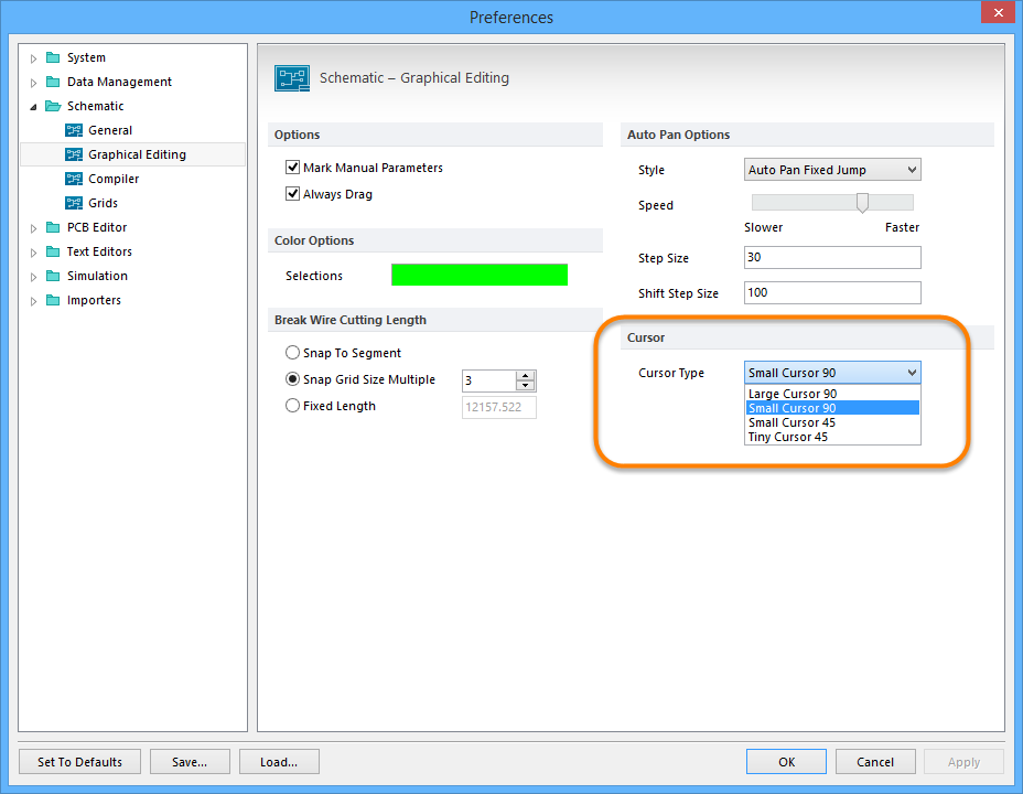
You can also change the Cursor type to suit your needs in the Cursor section of the Schematic - Graphical Editing page of the Preferences dialog.
Placing Design Objects
Tips for placing schematic objects:
- Click the button on the Ribbon for the object type that you want to place. To place components (parts), you can also click the Place button in the Libraries panel, double-click the component name in a library in the Libraries panel, or click on the name and drag it onto the document.
- When an object is being placed, the cursor will change to a crosshair to indicate that you are in editing mode, and the object will appear floating on the cursor.
- Press Tab to edit the properties of the object before placing it. The advantage of editing during placement are that objects that have a numeric identifier, such as a designator, will auto-increment. In addition, changes made during placement can become the defaults for that object type for the remainder of the current editing session.
- Press Spacebar to rotate the object, such as a component or a net label, while it is floating on the cursor. Press Shift+Spacebar to rotate in the other direction.
- Position the cursor then left-click or press Enter to place the object. For complex objects, such as wires or polygons, you then continue the position-and-click procedure to place all vertices (corners) of the object. Kkeep an eye on the Status bar for more information.
- For objects with a cornering mode, such as wires and buses, press Spacebar to toggle the direction of the corner and Shift+Spacebar to cycle through the available corner modes. Press Backspace to remove the last-placed corner.
- You can move around the document by moving the editing cursor (crosshair) so that it bumps the edge of the editing window. This is known as autopanning. Set the style and speed of autopanning in the Schematic - Graphical Editing page of the Preferences dialog.
- Zoom in / out as you work by: Ctrl+Wheel roll up / down, or PgUp / PgDn, or Ctrl+Right-click and drag up / down.
- Pan across the document by bumping the edge of the edit window when the edit cursor (crosshair) is displayed, or right-click and drag to display and use the panning hand cursor.
- After placing an object, you will remain in placement mode for that object, allowing you to immediately place another object of the same type. Right-click or press Esc to end placement mode. In some cases, such as placing a polygon, you need to do this twice; once to finish placing the object and a second time to exit placement mode.
Morphing an Object
An excellent time saving feature included in the schematic editor is the ability to morph object attributes from a placed object into the object currently floating on the cursor. Press Insert to morph possible attributes.
When Insert is pressed, the Net attribute is morphed from the Port into the floating Net Label.
Wiring the Schematic
Wires are used to create the electrical connections between points in the schematic.
- A wire must fall on the connection point of an electrical object to be connected to it, for example, a point along a wire must fall on the end of a pin to connect to that pin. As you are placing, when the wire falls within the electrical grid range of another electrical object, the cursor will snap to the fixed object and a hotspot (red cross) will appear. This hotspot guides you to where a valid connection can be made, automatically snapping the cursor to electrical connection points. The wire will be automatically terminated when you click to connect it to a hotspot.
- It is recommended that you set the Electrical grid to be slightly smaller than the current Snap grid; otherwise in certain circumstances, it can become difficult to position electrical objects one snap grid apart.
- If you want to place a wire that does not yet connect to another electrical object, right-click (or press Esc) to terminate the wire.
- While placing a wire or bus, use the Backspace key to delete the last vertex placed.
- Right-click or Esc a second time to exit wire placement mode.
It is the wiring that creates the connectivity in the schematic.
Wire/Bus Placement Modes
Wires and buses support a number of modes that define how the corners are created.
- The following wiring modes are available:
- 90 Degree
- 45 Degree
- Any Angle
- Auto Wire
- When placing a wire or bus, press Shift+Spacebar to cycle through the corner modes.
- When placing a wire or bus, press Spacebar to toggle between the Start and End sub-modes (when in 90 Degree or 45 Degree modes), or between Any Angle and Auto Wire modes (when either of these modes is active).
The Auto Wire mode is a special mode that allows you to automatically connect two points on the schematic, automatically routing the wire around obstacles between those two points. When in this mode, press the Tab key to set the Autowirer options in the Point to Point Router Options dialog.
Junctions
The software will automatically add a junction when a wire is placed so that it forms a T with an existing wire.
- Autojunctions have the same dark blue color as wires.
- Place a manual junction if you need to create a 4-way junction on your schematic. Press Tab while placing to change the color.
- The display, junction size and color of auto-junctions can be configured on the Schematic - Compiler page of the Preferences dialog.
- Cross-overs can be displayed as a small bridge, or as a simple wire-crosses-wire. Configure the style on the Schematic - General page of the Preferences dialog.
Auto-junctions have the same color as wires. Note the selected cross-over style.
Editing Design Objects
Any design object you have placed in a schematic or a PCB can be modified in a variety of ways.
- Graphically - many of the design objects can be resized by moving their editing handles. Click to select the object and display the handles.
- The object's dialog - double-click to edit the properties of any object in a dedicated properties dialog.
- The Inspector panel - the Inspector panel is enabled on the View tab of the Ribbon and is similar to the object properties dialog in that it lists all of the properties of the object. Click once to select an object and display its properties in the Inspector panel. Advantages of the Inspector panel include: as a panel it can always be displayed, making it easy to quickly move from one object to another; and it show the settings of all currently selected objects, so can be used to edit multiple objects in a single action. This is a powerful feature that you will find very useful during the design process.
Selected objects can also be moved around within the document (click-and-drag), and cut, copied, and pasted using the standard Windows shortcuts within and between documents.
Placed components (parts) and footprints can be edited through properties dialogs or changed in their Library Editors and updated. Schematic component pins can also be edited on the schematic using the Component Pin Editor, available from the schematic Component Properties dialog (click the Edit Pins button).
Graphically Editing Placed Objects
It is generally easier to edit the look of an object in the workspace graphically. To do this, you must first select the object(s) to display the editing vertices.
When an object is selected, you can move the object or edit its graphical characteristics. Click on an object to select it; its 'handles' or vertices are displayed. To graphically change a selected object, click and hold on an editing handle. That point of the object will then become attached to the cursor. Move the mouse to a new location and release to resize. Click anywhere on a selected object to move it or press the Delete key to delete it.
Modifying the Wiring
There are several ways you can change a placed wire — by moving a vertex, moving a segment, moving the entire wire, or extending the wire to a new location. You can also edit, add or remove vertices through the Vertices tab in the wire's properties dialog. The following animation shows a number of interactive wire editing techniques. Keyboard and mouse actions are shown using icons, the following icons show the mouse actions:
| Left-click | |
 | Left-click + drag |
Left-click and drag to modify a wire, Ctrl+click and drag to move a wire. Note that all selected segment ends will drag together.
| Action | Process |
|---|---|
| Move a segment | Click and drag the segment to its new location. |
| Move a Vertex | Click on the wire to select it, position the cursor on the vertex you want to move until the cursor changes to a double arrow, then click and drag the vertex to its new location. |
| Move an entire wire | To move the entire wire without modifying the wire shape or maintain connectivity, Ctrl+click and drag. |
| Extending a wire | Select the wire and position the cursor on the end vertex you want to move until the cursor changes to a double arrow. Click on the endpoint and drag to the new location, then release. You can change the placement mode while moving the cursor to the new location by using Shift+Spacebar. |
| Deleting a segment | Click once to select the entire wire (each vertex is shown in the selection color), then click a second time to select the required segment; its vertices will become red. Click the Delete key on the keyboard to remove that segment. |
Breaking a Wire
![]()
The Break Wire cutting tool
Use the Break Wire command to break a wire segment into two pieces (Tools | Convert | Break Wires). This command is also available from the right-click menu when the cursor is over a wire.
- A cutter box displays (by default) which automatically locks onto the wire to be cut.
- The section to be cut out is masked, as shown in the image above. Press Spacebar to cycle through the three cutting length modes (snap to segment, snap grid size multiple, or fixed length).
- Press Tab to set the fixed cutting length and other cutter options.
- Click to break the wire.
- Right-click or press Esc to exit break wire mode.
- Break Wire options can also be set in the Schematic - Graphical Editing page of the Preferences dialog.
Moving or Dragging Schematic Objects
- Move - the term Move is used to describe what happens when you move an object to reposition it without regard to objects in contact with it. For example, moving a component will ignore the wires connected to it.
- Drag - the term Drag is used to describe what happens when you move an object and want the software to attempt to maintain connectivity. When you drag a component, attached wires shrink/stretch to maintain connectivity.
Tips for Moving or Dragging Objects
- You can move single, non-selected objects or multiple selected objects using Click-and-drag to drag the object(s) or Ctrl+click-and-drag to move the object(s).
- You can also use the commands in the Tools | Arrange | Move menu especially if you want to move an object to the front or back of other placed objects.
- When you move/drag a component, the cursor will jump to the nearest electrical hotspot, which is the end of the nearest pin. Pre-position the cursor to grab the component by a specific pin.
- While objects are being moved or dragged:
- Press Spacebar to rotate the object(s) in 90° steps counterclockwise; press Shift+Spacebar to rotate clockwise.
- Press the X or Y keys to flip the object along the X-axis or Y-axis respectively.
- Hold down the Alt key to constrain the direction of movement to the horizontal or vertical axis (start moving/dragging, then press Alt) .
- You can Move selected objects in increments of the grid without the mouse using a combination of the Ctrl+arrow key (vertically or horizontally). Add Shift to step in increments of 10x the grid.
- Press G to cycle through the available grid settings while moving/dragging - the current grid setting is shown on the Status bar.
Multi-Wire Dragging
The multi-wire editing mode in the schematic editor allows you to extend multiple wires at the same time. If multiple parallel wires share a coordinate for their end vertex, when you click and drag to move the end of one wire vertex, the end vertex of all other selected wires will also move, keeping the wire ends aligned.
Drag and release one vertex; all selected vertices will move to remain aligned.
Locking Objects from Moving
To prevent schematic objects from being moved inadvertently, you can enable the Locked property for those objects to protect them from being edited graphically. If you try to edit a locked design object, you will be prompted with a Confirm dialog and asked if you want to go ahead with the action.
Copy and Paste
The schematic editor includes standard Windows copy/paste behaviors. In the Schematic editor:
- Copy and paste objects within or between schematic documents, e.g., component(s) from a schematic can be copied into another schematic document.
- You can copy component(s) from a schematic and paste them into an open schematic library. to do this, right-click in the SCH Library panel then select Paste.
- You can copy objects to the Windows clipboard and paste them into other documents.
- Text can be copied from the Windows clipboard into a schematic text frame.
- You can copy/paste a table-type selection from another application, such as Microsoft Excel, or from any grid style control within Altium Designer.
On-sheet Text Editing
Text strings can be edited directly on the schematic sheet. Click once to select a text string, text frame or note, then click a second time to edit the string directly on the schematic sheet (or press the F2 shortcut key).
Annotation and Re-Annotation
There are two approaches to annotating your design in Altium Designer: schematic annotation or PCB re-annotation. In the schematic editor, use the Tools | Annotation | Annotate » Annotate Schematics command to open the Annotate dialog.
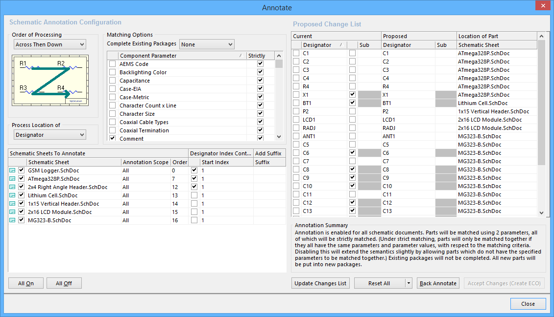
The schematic annotation feature is a:
- Positional annotation process, working across each sheet in the pattern selected in the Order of Processing drop-down, and through the sheets according to the Order defined in the Schematic Sheets To Annotate region of the dialog.
- For each sheet, you can also control the Start Index and include a Suffix using the associated options.
- Multi-part components are packaged together using the Matching Options.
- Use the Annotate Schematics Quietly command to assign a unique designator to any component that is currently not designated without launching the Annotate dialog. This command obeys the configuration you have previously set up in the dialog. Note that the Annotate Schematics Quietly command does not attempt to resolve duplicate designators.
- Use the Force Annotate All Schematics command to re-annotate all component designators in accordance with the last configuration defined in the Annotate dialog.
- In the PCB editor, use the Tools | Annotation | Re-Annotate command to open the Positional Re-Annotate dialog, where you can reassign the designators based on the components' locations on the board.
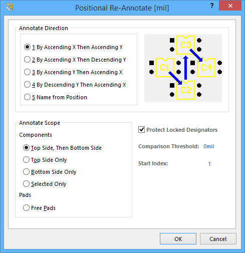
Designators can also be re-assigned positionally in the PCB editor.
Non-Graphical Editing
To view or edit the properties of any object:
- When an object is 'floating' on the cursor during placement, press Tab to open its properties dialog.
- Double-click on a placed object to open its properties dialog.
- Click on a placed object to select it, then edit its properties in the SCH Inspector panel as described below.
Editing Objects in the SCH Inspector Panel
The SCH Inspector panel enables you to examine and edit the properties of one or more design objects in the current or open document(s).
Select one or more objects then press F11 to display the SCH Inspector panel.
Note that the SCH Inspector panel only shows properties that are common to all selected objects.
- At the top of the panel, there are two important options that control what gets included:
- Objects - use this option to reduce the types of selected objects that are loaded into the panel,
- Documents - configure from which schematic documents the targeted objects are to be included.
- Changes made in the Inspector panel are applied as soon as you press Enter or click on another cell.