PCB 3D Print Settings
Parent page: WorkspaceManager Dialogs
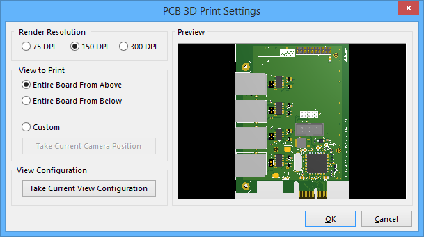
The PCB 3D Print Settings dialog
Summary
This dialog provides controls to define settings when generating a print of the board in 3D.
Access
The dialog is accessed in the following ways:
- With the PCB 3D Print entry selected on the Default Prints tab of the Options for PCB Project dialog, click the Configure button.
- Click the Configure control associated to the PCB 3D Print entry in the Generate output files dialog (Project | Project Actions |
 ).
). - If the PCB 3D Print output type is the default print for the PCB editor:
- Use the Outputs | Documentation | Print » Page Setup command then click the Advanced button in the PCB 3D Print Properties dialog.
- Use the Outputs | Documentation | Print » Print Preview command then right-click in the main previewing window and choose the Configuration command from the context menu.
Options/Controls
Render Resolution
Use this region to specify the quality of the "picture" of the 3D model to be printed in terms of a rendering resolution. Supported resolutions are 75 DPI, 150 DPI, and 300 DPI.
View to Print
Use this region to select the view of the board to be printed. Choose from the following supported options:
- Entire Board From Above - choose this option to print the 3D view of the board looking directly down from above the board (camera perspective perpendicular to the board).
- Entire Board From Below - choose this option to print the 3D view of the board looking directly up from below the board (camera perspective perpendicular to the board).
- Custom - choose this option then click the Take Current Camera Position button to print the 3D view of the board as it is currently displayed in the PCB editor.
View Configuration
Click the Take Current View Configuration button to apply the current workspace view configuration for surface colors, visibility and opacity, and board thickness.
Preview
This region presents a preview of what will be printed. It will dynamically update as changes are made in the View to Print and/or View Configuration regions of the dialog.