
Annotate
Contents
Parent page: WorkspaceManager Dialogs
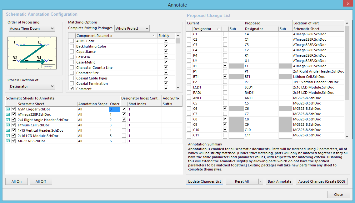
The Annotate dialog
Summary
The Annotate dialog provides controls to systematically assign designators to all (or selected parts) in selected schematic sheets of a project, and ensures that designators are unique and ordered based on their position. Annotation options can be configured to package multi-part components, set Index and Suffix options, and Reset Schematic Designators (including any duplicate designators).
Access
The dialog is accessed from the Schematic Editor by using the Tools | Annotation | ![]() » Annotate Schematics command from the main menus.
» Annotate Schematics command from the main menus.
Options/Controls
The dialog is partitioned into two primary regions:
- Schematic Annotation Configuration - this region is for configuring the annotation scheme, as well as the scope of annotation.
- Proposed Change List - this region lists the proposed changes that will occur once accepted and executed using an Engineering Change Order (ECO).
Schematic Annotation Configuration
Order of Processing
Use this region to specify the required method of positional annotation. As you select a method from the drop-down list, the associated graphical representation dynamically updates to illustrate how the components will be annotated. Choose from the following methods of positional annotation:
- Up Then Across
- Down Then Across
- Across Then Up
- Across Then Down
Process Location of
Use this region to specify the reference for component locations when processing the annotation order. Choose from the following:
- Designator - the component's designator is used as the reference for its location when determining processing order.
- Part - the center of the component is used as the reference for its location when determining processing order.
Matching Options
When using multi-part packages, it is often desirable to pack as many parts into the minimum number of physical parts since this minimizes the overall BOM cost of the design. The controls in this region allow you to define how components will be matched and grouped together, and the criteria used for determining valid groupings.
- Complete Existing Packages - use this control to decide if and how parts that are not annotated will be included in existing packages. Use the field's drop-down to choose from the following:
- None - existing packages will not be completed and all new parts will be placed into new packages.
- Per Sheet - existing packages will include only new parts from the same schematic sheet.
- Whole Project - existing packages will include new parts from any of the schematic sheets in the project.
- Component Parameter - this list includes all parameters found within components in the current design. Enable the checkbox associated with a parameter to use it for matching parts into packages. If multi-part components share the same enabled parameters and a common value, they will be packaged together (provided the Complete Existing Packages option is not set to None). Any remaining components that do not have the enabled parameter(s) are also packaged together.
- Strictly - enabling this option for a Component Parameter means that all components must have that parameter to be matched into a package. Components that do not have this parameter are annotated as individual components and are not packaged.
The following commands are available on the region's right-click menu:
- Parameter » Enable Selected Parameters - use this command to check the 'include' checkbox for all parameters currently selected in the list.
- Parameter » Enable All Parameters - use this command to check the 'include' checkbox for all parameters in the list.
- Parameter » Disable Selected Parameters - use this command to uncheck the 'include' checkbox for all parameters currently selected in the list.
- Parameter » Disable All Parameters - use this command to uncheck the 'include' checkbox for all parameters in the list.
- Match Strictly » Enable Strict Matching On Selected Parameters - use this command to enable the Strictly option for all parameters currently selected in the list.
- Match Strictly » Enable Strict Matching On All Parameters - use this command to enable the Strictly option for all parameters in the list.
- Match Strictly » Disable Strict Matching On Selected Parameters - use this command to disable the Strictly option for all parameters currently selected in the list.
- Match Strictly » Disable Strict Matching On All Parameters - use this command to disable the Strictly option for all parameters in the list.
- Selection » Select All - use this command to select all parameter entries in the list.
- Selection » Deslect All - use this command to deselect all parameter entries in the list.
- Selection » Invert Selection - use this command to select all parameters not currently selected in the list and deselect those that are.
Schematic Sheets To Annotate
This region lists all of the source schematic sheets in the design project. Controls available in this region are used to determine which sheets are to be included in the annotation process and the specifics of how annotation changes will be calculated. For each sheet, the following is presented:
- Include/Exclude checkbox - enable this checkbox to include the schematic sheet in the annotation process.
- Schematic Sheet - this field displays the name of the schematic sheet.
- Annotation Scope - use this field to determine the scope of annotation with respect to the components on the sheet. Use the field's drop-down to choose one of the following scopes:
- All - all parts on the schematic sheet will be annotated.
- Ignore Selected Parts - all parts, except those currently selected in the design, will be annotated.
- Only Selected Parts - only those parts currently selected in the design will be annotated.
- Order - use this field to specify where, in the overall order of sheet annotation, this sheet is to be placed. Type the desired order number directly into the field or use the arrows that appear once you click in the field to scroll to your preference.
- Designator Index Control - use the controls in this column to enable the use of a start index (by checking the associated checkbox) and defining a value for the index. The designator value will begin from this index value.
- Add Suffix - use this field to specify use of a suffix to be appended to each annotated designator. Alpha (A, B, C...) numeric (1, 2, 3...) and non-alphanumeric (_ * . %...) suffixes are supported including a combination of these.
The following additional controls are available for this region:
- All On - click this button to include all schematic sheets in the annotation process.
- All Off - click this button to exclude all schematic sheets from the annotation process.
- Right-click Menu - the following commands are available from the region's right-click context menu:
- Order Alphabetically - use this command to order the list of schematics alphabetically. This will impact the associated Order entry for each sheet.
- Order By Project Order - use this command to order the list of schematics by the order in which they appear for the project (as seen on the Projects panel). This will impact the associated Order entry for each sheet.
- All On - use this command to include all schematic sheets in the annotation process.
- All Off - use this command to exclude all schematic sheets from the annotation process.
Proposed Change List
- Main List - this region of the dialog lists all designators for the parts contained within the sheets selected for annotation. For each entry, details of the Current and Proposed designator values are included, along with the component's Sub (part) and the source Location of Part. Checking the box adjacent to a designator in the Current column ('designator locked') will lock that specific designator from any changes. Similarly, checking the box adjacent to a designator's Sub field ('sub-part locked') will prevent that specific sub-part of the parent multi-part component from being updated.
The following commands are available on the region's right-click menu:
- Designator » Lock Selected Designators - use this command to check the 'designator locked' checkbox for all designators currently selected in the list.
- Designator » Lock All Designators - use this command to check the 'designator locked' checkbox for all designators.
- Designator » Unlock Selected Designators - use this command to uncheck the 'designator locked' checkbox for all designators currently selected in the list.
- Designator » Unlock All Designators - use this command to uncheck the 'designator locked' checkbox for all designators.
- Part ID » Lock Selected Part ID - use this command to check the 'sub-part locked' checkbox for all designators currently selected in the list.
- Part ID » Lock All Part ID - use this command to check the 'sub-part locked' checkbox for all designators.
- Part ID » Unlock Selected Part ID - use this command to uncheck the 'sub-part locked' checkbox for all designators currently selected in the list.
- Part ID » Unlock All Part ID - use this command to uncheck the 'sub-part locked' checkbox for all designators.
- Selection » Select All - use this command to select all designator entries in the list.
- Selection » Select All With '?' - use this command to select all entries whose current designator contains ? (i.e. have been reset).
- Selection » Deselect All - use this command to deselect all designator entries in the list.
- Selection » Invert Selection - use this command to select all designators not currently selected in the list and deselect those that are.
- Annotation Summary - this area provides a summary of the annotation, in terms of the number of sheets involved and the matching options. It dynamically updates as changes are made to these areas.
- Update Changes List - click this button to update the main proposed changes list with new calculated changes based on defined annotation settings on the left side of the dialog. An information dialog will present details of how many changes were made since the previous state and how many changes were made since the original state.
- Reset All - click this button to reset all designators in the main list (that are not locked) to their default component prefixes, e.g., R?, C?, D?. The changes will be loaded in the Proposed designators column. The button's drop-down allows you to change the rest command to Reset Duplicates. If two or more components have the same designator, all but one will be reset to their default prefixes. An information dialog will present details of how many changes were made since the previous state and how many changes were made since the original state.
- Back Annotate - click to open a dialog to search for and select the file for back annotation.
- Accept Changes (Create ECO) - after reviewing all proposed changes, click this button to access the Engineering Change Order dialog, listing the proposed changes as modifications within the modification category Annotate Component. Use this dialog to validate and execute the ECO, completing the Annotation Process at the schematic level.