Net Label
Contents
Parent page: Schematic Objects

Net labels identify and electrically connect different points in a schematic.
Summary
Electrical connectivity between schematic component pins can be created by placing a wire between those pins. This is called physical connectivity snce the pins are physically connected with a wire. Connectivity can also be created logically by using suitable net identifiers, such as net labels. As well as providing a human-friendly identifier for a net, a net label allows you to connect points on a circuit without actually physically wiring them together.
Availability
Net labels are available for placement in the Schematic Editor only by clicking Home | Circuit Elements | ![]() from the main menus.
from the main menus.
Placement
After launching the command, the cursor will change to a cross-hair and you will enter net label placement mode with a net label floating on the cursor:
- Press Tab to open the Net Label dialog. The Net property will be the active control in the dialog and the existing text selected ready for editing. Type in the new net name then press Enter to close the dialog.
- If the net label requires rotation, press the Spacebar to rotate it in 90° increments. Press the X or Y keys to flip the net label along the X-axis or Y-axis respectively.
- Position the net label so that its bottom-left corner touches the object to which you want to assign it, then click or press Enter to place the net label.
- Continue placing further net labels, or right-click or press Esc to exit placement mode.
Graphical Editing
The net label can be edited graphically, using what is known as in-place editing. To edit a net label string in-place, click once to select, pause for a second, then click a second time to enter edit mode.
 Click once to select the string.
Pause, then click a second time to enter in-place edit mode.
Here the string has been selected, ready to type in a replacement string.
The Net Label can be edited in-place.
Once editing is complete, press Enter or click away from the string to exit in-place editing mode.
Non-Graphical Editing
The following methods of non-graphical editing are available:
Via an Associated Properties Dialog
Dialog page: Net Label
This method of editing uses the Net Label dialog to modify the properties of a net label object.
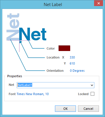
The Net Label dialog
The dialog can be accessed during placement by pressing the Tab key.
After placement, the dialog can be accessed in one of the following ways:
- Double-click on the placed net label object.
- Place the cursor over the net label object, right-click then choose Properties from the context menu.
Via the SCH Inspector Panel
Panel page: SCH Inspector
The SCH Inspector panel enables you to interrogate and edit the properties of one or more design objects in the active document.
Notes
- Net labels create logical connectivity within a single schematic sheet; they do not create connectivity between schematic sheets. To do this, Ports must be used.
- To negate (include a bar over the top of) a net label, include a backslash character after each character in the net name (e.g., E\N\A\B\L\E).
- When individual nets form a bus, there are specific requirements as to how they are named. For more information refer to the Bus page.
- Net identifiers of different types do not automatically connect to one another even if they share the same name. For example, a net label named AGND will not automatically connect to a power port named AGND; a wire must be placed to connect them.