Coordinate
Contents
Parent page: PCB Objects

A placed Coordinate
Summary
A coordinate is a group design object. It is used to mark the X (horizontal) and Y (vertical) distance of a point in the design workspace relative to the current origin. Coordinates can be placed on any layer.
Availability
Coordinates are only available for placement in the PCB Editor by clicking Home | Place | ![]() from the main menus.
from the main menus.
Placement
After launching the command, the cursor will change to a cross-hair and you will enter coordinate placement mode. A coordinate will appear "floating" on the cursor:
- Position the cursor then click or press Enter to place a coordinate.
- Continue placing further coordinates, or right-click or press Esc to exit placement mode.
Additional actions that can be performed during placement are:
- Press the L key to flip the coordinate to the other side of the board.
- Press the + and - keys (on the numeric keypad) to cycle forward and backward through all visible layers in the design, respectively, to change placement layer quickly.
- Press the Tab key to access an associated properties dialog, from where properties for the coordinate can be changed on-the-fly.
Graphical Editing
This method of editing allows you to select a placed coordinate object directly in the workspace and change its location graphically. The size and shape of a coordinate object cannot be changed graphically. As such, editing handles are not available when the coordinate object is selected:
A selected Coordinate
- Click anywhere on the coordinate and drag to reposition it. The position values are automatically updated as the coordinate is moved.
Non-Graphical Editing
The following methods of non-graphical editing are available:
Editing via an Associated Properties Dialog
Dialog page: Coordinate
This method of editing uses the following dialog to modify the properties of a coordinate object.
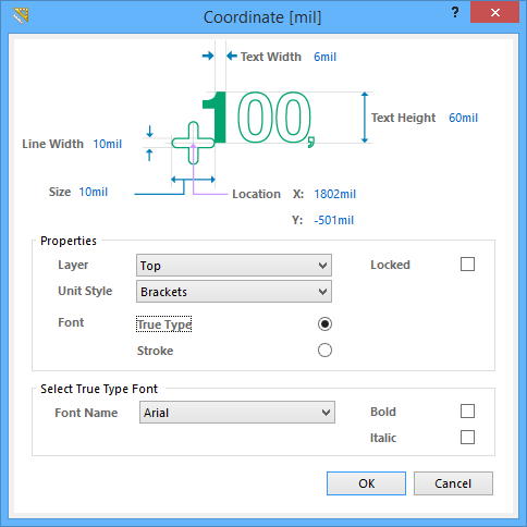
The Coordinate dialog
The Coordinate dialog can be accessed during placement by pressing the Tab key.
After placement, the dialog can be accessed in one of the following ways:
- Double-click on the placed coordinate object.
- Place the cursor over the coordinate object, right-click then choose Properties from the context menu.
Editing via an Inspector Panel
Panel pages: PCB Inspector, PCBLIB Inspector
An Inspector panel enables you to interrogate and edit the properties of one or more design objects in the active document. Used in conjunction with appropriate filtering, the panel can be used to make changes to multiple objects of the same kind, from one convenient location.
Notes
- The current origin can be set to be any point in the PCB workspace by selecting Home | Grids and Units | » Set then clicking on the location for the new origin. To set the current origin back to the absolute origin (
(0,0), in the lower-left corner of the workspace), select Home | Grids and Units | » Reset.