PCB Editor - General
Contents
Parent page: PCB Preferences
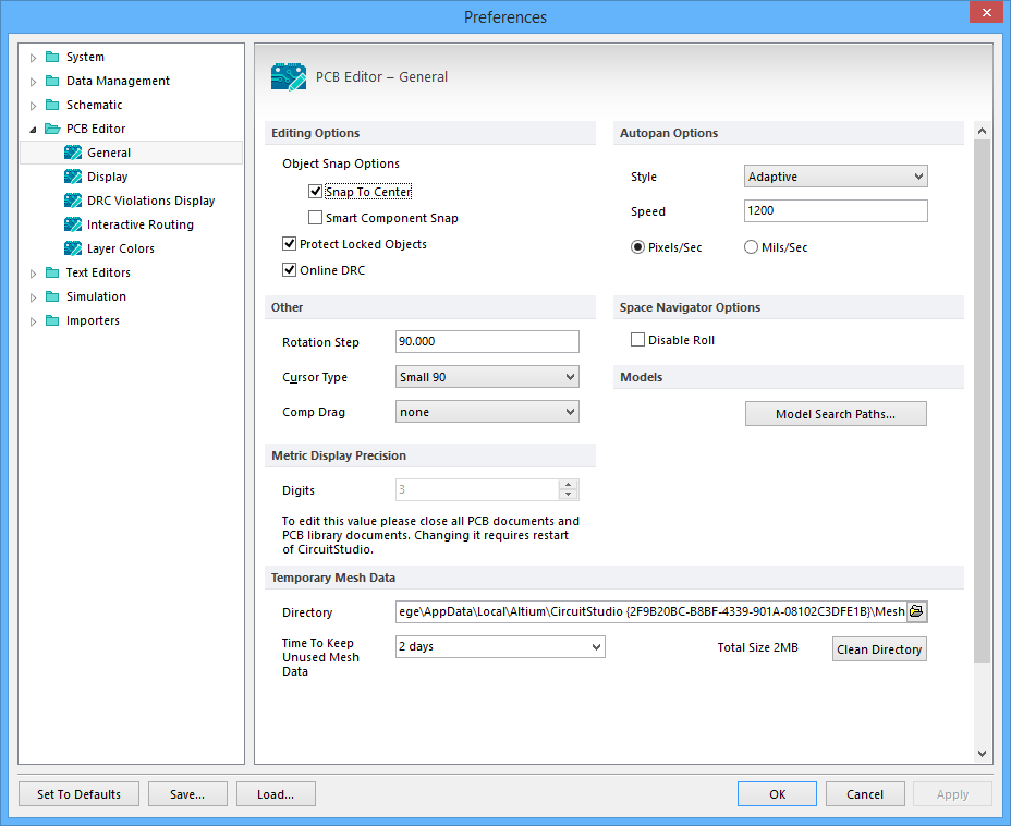
The PCB Editor - General page of the Preferences dialog
Summary
The PCB Editor – General page of the Preferences dialog provides a range of configuration controls relating to the PCB Editor within the PCB workspace.
Access
The PCB Editor – General page is part of the main Preferences dialog (File | ![]() ) and is accessed by clicking the General entry under the PCB Editor folder in the left hand pane of the dialog.
) and is accessed by clicking the General entry under the PCB Editor folder in the left hand pane of the dialog.
Options/Controls
Editing Options
- Object Snap Options
- Snap To Center - Enable to have the cursor jump automatically to a defined reference point on an object when it is selected and be 'held' by that point as it is repositioned. When moving a free pad or via, the cursor will snap to the center of the object. When moving a component, the cursor snaps to the component's reference point. When moving a track segment, the cursor snaps to the vertex point. If this option is disabled, objects will be 'held' by the point where they have been selected.
- Smart Component Snap - If enabled, when a component is clicked to select it, the cross hair cursor appears on the nearest pad of this component in respect to the cursor location. Disable this option so that the cross hair cursor always appears on the component's pad reference point when it is clicked on.
- Protect Locked Objects - Enable to ignore any selected locked objects if they are part of a selection that is being moved.
- Online DRC - Enable to have software monitor all PCB design rules interactively (online) as you work and immediately highlight any rule violations. If this option is disabled, design rule violations will not be highlighted as you work. Violations will only be highlighted when you manually run a Design Rule Check.
Autopan Options
- Style - Use this field to set the style of document autopanning. With autopanning enabled, when the crosshair cursor is active during any editing action, moving the cursor past any edge of the document view window will cause the document to pan in the relevant direction. The following styles are available:
Disable- Autopan is deactivated.Re-Center- Re-centers the display around the location where the cursor touched the edge of the main design window. It also holds the cursor position relative to its location on the board, bringing it back to the center of the display.Fixed Size Jump- Pans across in steps defined by the Step Size value (available whenFixed Size Jumpis selected). Hold the Shift key to pan in steps defined by the Shift Step value (available whenFixed Size Jumpis selected).Shift Accelerate- Pans across in steps defined by the Step Size value (available whenShift Accelerateis selected). Hold the Shift key to accelerate the panning up to the maximum step size defined by the Shift Step value (available whenShift Accelerateis selected).Shift Decelerate- Pans across in steps defined by the Shift Step value (available whenShift Decelerateis selected). Hold the Shift key to decelerate the panning down to the minimum step size defined by the Shift Size value (available whenShift Decelerateis selected).Ballistic- The panning will increase from the Step Size value to Shift Step value (both available whenBallisticis selected) dependent on how far past the edge of the viewing window you move the cursor. Hold the Shift key to pan in steps defined by the Shift Step value (available whenBallisticis selected).Adaptive- (Default) The panning will move at a constant speed when the cursor reaches the edge of the PCB window. When there are no design objects in the region where the panning is taking place, the cursor speed slows down.
- Speed - Shows the current autopanning speed. Edit this field to change the speed. The measurement is set according to the Pixels/Sec or Mils/Sec options.
- Pixels/Sec - Select this option to set autopanning speed in pixels per second. The number of pixels per second is set in the Speed field.
- Mils/Sec - Select this option to set autopanning in mils per second. The number of mils per second is set in the Speed field.
Other
- Rotation Step - Shows the amount of rotation, in degrees, applied to objects floating on the cursor when the Spacebar is pressed. Edit this field to change the angle (default is 90°). Minimum angular resolution is 0.001°. Pressing the Spacebar when an object is floating on the cursor rotates the object by the set number of degrees in a counterclockwise direction. Hold the Shift key while pressing the Spacebar to rotate in a clockwise direction.
- Cursor Type - Defines the shape of the 'action' cursor. This cursor is displayed whenever any editing action is performed (such as placing or moving and object). Click to view and select a cursor type from the list. Available cursors are:
Large 90- Cursor consists of intersecting horizontal and vertical lines spanning the width of the screen.Small 90- Small crosshair cursor angled at 90° (e.g., +). This is the default.Small 45- Same as Small 90 except that the cross-hair lines are at a 45° (e.g., X).
- Comp Drag - Shows how connected tracks are handled when a component is dragged. To drag a component, select Tools | Arrange | Move | Drag from the main menus then click on the component to be dragged. Click to view and select an option from the list. Available options are:
None- Only the component moves when it is dragged. Any attached tracks will be disconnected and left in place.Connected Tracks -Any connected tracks will remain attached to the component when it is dragged.
Space Navigator Options
- Disable Roll - Check this option to disable the Space Navigator function.
Models
The Model Search Paths button opens the Model Search Path dialog.
- The main body of the dialog lists the current STEP model file search path(s), which includes the default folders that will be included when linking 3D STEP model files via the 3D Body dialog. You could consider these folders 'watched' in that the software monitors changes to STEP files (
*.stp,*.step) they contain. - Click
 in the path field to browse for a suitable folder via the Browse for Folder dialog, the, add it to the model search path list using the Add button. Whenever a STEP model is linked to a component footprint or PCB document, the folders listed in the Model Search Path dialog list are defaulted to. The concept of using common or central depositories for STEP model files can be beneficial, particularly in multi-user environments.
 - Add - Click to add the folder currently displayed in the browser bar to the model search path list.
- Delete - Click to remove the currently selected folder from the model search path list.
Metric Display Precision
- Digits - Shows the number of significant digits to the right of the decimal point to display when showing metric values. The last digit will be rounded as required, however, calculations within the system are always performed at the base system resolution. For example, if the initial value was calculated as "5.254667", the display would show:
- "5.255" @ 3 digit precision
- "5.2547" @ 4 digit precision
- "5.25467" @ 5 digit precision
Temporary Mesh Data
Mesh data is calculated for display purposes when a 3D model is first used or created. This data is saved and reused whenever that model is required. Storing mesh data in this way can improve system performance when working in the 3D workspace.
- Directory - Click the browse icon to browse for a folder via the Browse for Folder dialog, in which software will store 3D model mesh data.
- Time to Keep Unused Mesh Data - Click to view and select a maximum period of time (in days) for the system to store 3D model mesh data since its last use before it is automatically deleted.
- Clean Directory - Click to immediately empty the folder used to store temporary 3D model mesh data.