
Text
Contents
Parent page: PCB Dialogs
The Text dialog
Summary
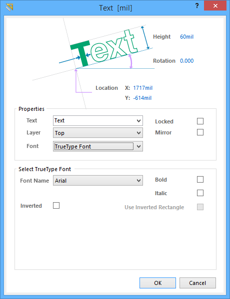
The Text dialog provides controls to enter text and edit the text properties. Text (also known as strings) is a standard element of a PCB design that is used to add detail and human-readable information.
Access
The Text dialog can be accessed during placement by pressing the Tab key.
After placement, the dialog can be accessed in the following ways:
- Double-click on the placed object.
- Place the cursor over the object, right-click then choose Properties from the context menu.
Options/Controls
- Width - Specify the width of the text.
- Height - Specify the height of the text.
- Rotation - Specify the rotation of the text. The minimum angular resolution is 0.001 degrees.
- Location X/Y - Specify the location of the text.
Properties
- Text - Enter the content. The software also supports a defined set of special strings that act as placeholders for PCB design or system-based information, such as layer names, hole counts, legends, etc., special strings can be selected using the drop-down. To learn more about special strings, read the Text Object article.
- Layer - Specify on which layer the text is located.
- Font - select the desired font type:
- TrueType Font - select to use fonts available on your PC (in the \Windows\Fonts folder). TrueType fonts offer full Unicode support.
- Stroke Font - select to use Stroke fonts.
- Locked - Enable this option to lock the text.
- Mirror - Enable this option to mirror the text.
Select TrueType Font
- Font Name - use this field to choose the required TrueType font. The drop-down list is populated with TrueType and OpenType (a superset of TrueType) fonts found in the \Windows\Fonts folder. Note, the list will only include entries for detected (and uniquely named) root fonts. For example, Arial and Arial Black will be listed but Arial Bold, Arial Bold Italic, etc., will not. Use the Bold and Italic options to add emphasis to the text.
- Bold - enable this option to make the dimension text bold.
- Italic - enable this option to make the dimension text italic.
- Inverted - enable this option to display the text as inverted within a layer-colored bounding rectangle.
- Use Inverted Rectangle - enable to use and inverted rectangle. This option is accessible only if Inverted is selected.
- Size (Width / Height)
- Width - enter the desired width.
- Height - enter the desired height.
- Justification - click the circle of select the desired justication.
- Inverted Text Offset - enter the desired offset.
- Size (Width / Height)
- Inverted Border - use this field to specify the border around the text. The bigger the border, the larger the resulting bounding rectangle. This field is available only when Inverted is enabled.
Select Stroke Font
- Font Name - use the drop-down to select the desired Stroke font. Choices are:
- Default - a simple vector font designed for pen plotting and vector photo plotting.
- Sans Serif - a complex font that will slow down vector output generation, such as Gerber.
- Serif - a complex font that will slow down vector output generation, such as Gerber.
Special Strings
As well as using a text object to place user-defined text on the current PCB layer, the text object can also be used to display design, system or user information on the PCB. This is done by placing what is known as a special string, which is a pre-defined string preceeded by the "." (dot) character. Refer to the Text object page for more information about special strings.