
Region
Parent page: PCB Dialogs
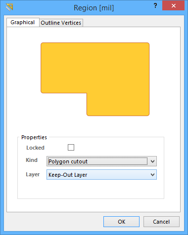
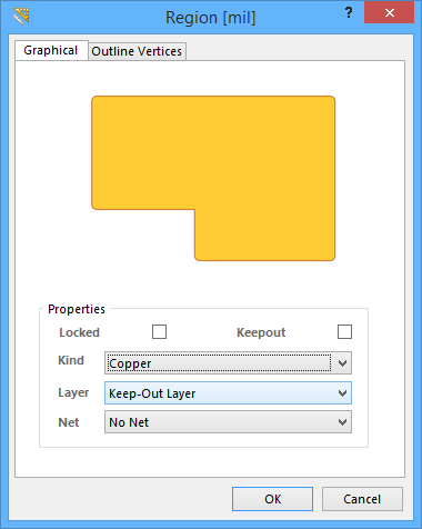
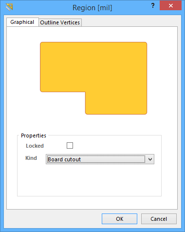
The Region dialog (showing Kind Polygon cutout, Copper, and Board cutout variations)
Summary
This dialog provides controls to specify the properties of a Region object. A Region, also known as a Solid Region, is a polygonal-shaped primitive object that can be placed on any layer. It can be configured to be positive, for example, placed as a copper region, or negative, for example, placed as a polygon pour cutout. By placing it as a negative on the multi-layer, it can be placed as a board cutout.
Access
The Region dialog can be accessed during placement by pressing the Tab key.
After placement, the dialog can be accessed in the following ways:
- Double-click on the placed region object.
- Place the cursor over the region object, right-click then choose Properties from the context menu.
Options/Controls
Graphical Tab
Region dialog - Graphical tab
Use the dialog's Graphical tab to modify graphical properties of the region object.
Properties
- Locked - enable this option to protect the region from being edited graphically.
- Keepout - this option is only available when Kind is set to Copper. Enable this option to define the region as a keepout. A keepout object is used on a signal layer to create a layer-specific keepout. Layer-specific keepouts are not included during output generation.
- Kind - Choose the function of the region:
- Copper - this kind of region is a solid, positive area that can be placed on any design layer, such as a signal (copper) layer.
- Polygon cutout - this kind of region functions as a polygon cutout, defining a negative, or no-copper area, within a polygon. Repour the polygon after placing a Cutout.
- Board cutout - this kind of region functions as a board cutout, defining a negative area, or hole, within the board shape.
- Layer - this field is only available when Kind is set to either Copper or Polygon Cutout. Use it to specify the layer on which the region is placed. All defined (and enabled) layers for the active board design will be listed in the drop-down list.
- Net - this field is only available when Kind is set to Copper. Use it to choose a net for the region. All nets for the active board design will be listed in the drop-down list.
Outline Vertices Tab
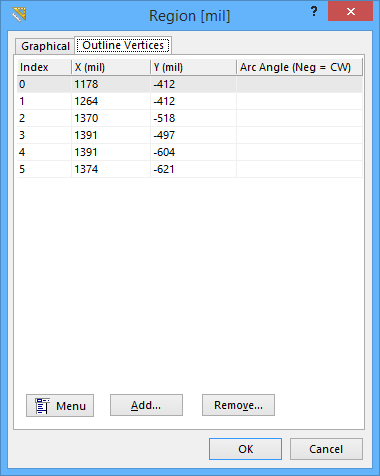
Region dialog - Outline Vertices tab
Use the Outline Vertices tab to modify the individual vertices of the currently selected region object. You can modify the locations of existing vertices, add new vertices, or remove them as required. Arc connections between vertex points can be defined, and support is also provided for exporting vertex information to and importing from a CSV-formatted file. You can also adjust the position of the region object by globally applying delta-x/delta-y values to all vertex points.
- Vertices Grid - the main region of the tab lists all of the vertex points currently defined for the region in terms of:
- Index - the assigned index of the vertex (non-editable).
- X - the X (horizontal) coordinate for the vertex. Click to edit.
- Y - the Y (vertical) coordinate for the vertex. Click to edit.
- Arc Angle - the angle of an arc that is drawn to connect this vertex point to the next. By default, connections are straight line edges, with this field remaining blank. Click to edit then enter an arc angle, as required. Entry of a positive value will result in an arc drawn counterclockwise. To draw a clockwise arc, enter a negative value.
- Add - click this button to add a new vertex point. The new vertex will be added below the currently focused vertex entry and will initially have the same coordinates as the focused entry.
- Remove - click this button to remove the currently selected vertex entry(ies) in the list. This command will be unavailable if there are only two vertices present for the region.
- Menu - click this button to access a pop-up menu containing the following commands:
- Edit - right-click on a coordinate cell (X or Y) for a vertex or its associated Arc Angle cell then use this command to edit the value in that cell. Alternatively, click directly on the cell.
- Add - use this command to add a new vertex point. The new vertex will be added below the currently focused vertex entry and will initially have the same coordinates as the focused entry.
- Remove - use this command to remove the currently selected vertex entry(ies) in the list. This command will be unavailable if there are only two vertices present for the region.
- Copy - use this command to copy the content of the selected cells in the list to the clipboard (or use Ctrl+C).
- Paste - use this command to paste the content of the clipboard into the list starting at the selected cell (o use Ctrl+V).
- Export To CSV - use this command to export all vertices to a CSV-formatted file (*.csv). The full list will be exported so there is no need to select anything prior to launching this command. Use the subsequent Export Outline Vertices dialog to determine where and under what name the file is to be saved.
- Import From CSV - use this command to import vertices from a CSV-formatted file (*.csv). Use the Import Outline Vertices dialog to browse to and open the required CSV file. The contents of the file will completely overwrite existing vertices.
- Select All - use this command to quickly select the entire grid contents of the list.
- Select Column - use this command to quickly select the entire column in which the currently focused cell resides.
- Move Up - use this command to move the selected vertex upward in the list.
- Move Down - use this command to move the selected vertex downward in the list.
- Move By XY - use this command to move the entire region object. The Move By dialog will open from where you can enter the increment value to be applied to each vertex point's X and Y coordinates.