
Polygon Pour
Contents
Parent page: PCB Dialogs
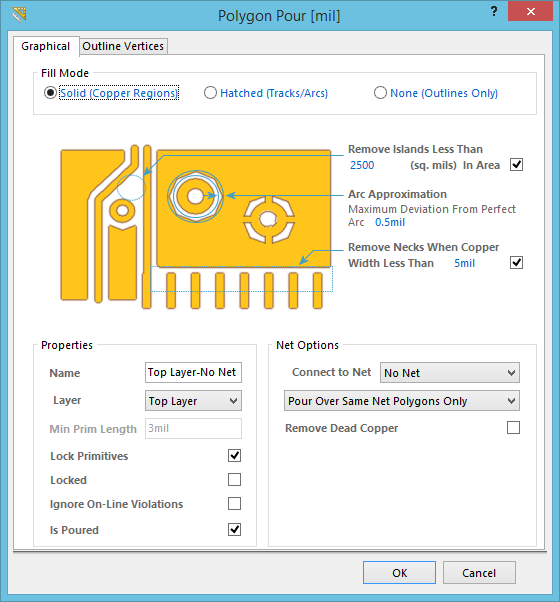
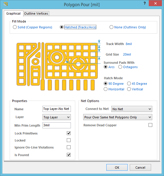
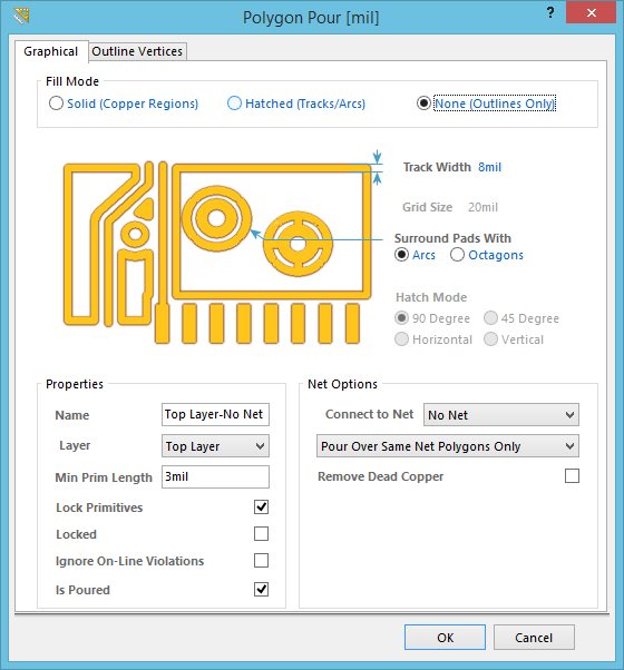
The Polygon Pour dialog in Solid mode, Hatched mode and None mode.
Summary
This dialog provides controls to specify the settings for a polygon pour. A polygon pour is a group design object - that is, it is made up of simpler primitive objects. Polygon pours are used to create either a solid or a hatched (lattice) area on a PCB layer using either Region objects, or a combination of Track and Arc objects. Also referred to as copper pours, polygon pours are similar to a region except that they can fill irregularly shaped areas of a board since they automatically pour around existing objects, connecting only to objects on the same net as the polygon pour.
Access
The dialog can be accessed during placement:
In the PCB Editor, click Home | Pour | ![]() (click on the image of the button).
(click on the image of the button).
After placement, the dialog can be accessed in the following ways:
- Double-click on the polygon.
- Place the cursor over the object, right-click then choose Properties from the context menu.
Options/Controls
Graphical Tab
Fill Mode
Click to choose one fill mode for the polygon pour. There are three modes available, each with their own advantages and roles:
- Solid (Copper Regions) - Region based polygons result in far fewer objects being placed, making for: smaller files, faster redraws, file opening, DRC and net connectivity analysis, and smaller output files since the region object is fully supported in Gerber and ODB++.
-
- Remove Islands Less Than - Specify an area value; any islands of polygon whose area is smaller than this value will be removed.
- Arc Approximation - Specify the maximum deviation from a perfect arc (curved edges are created from multiple short, straight edges when the Fill Mode is Solid (Copper Regions)).
- Remove Necks When Copper Width Less Than - Specify a width value; the polygon pour copper whose width is smaller than this value will be removed. Typically, this is set to be no smaller than the smallest width track used in the design or the smallest copper width supported by the fabricator.
- Hatched (Tracks/Arcs) - Track/Arc based polygons allow a hatched polygon to be created by setting the Track Width to be smaller than the Grid Size. Note that they can also be solid by setting the Track Width to be larger than the Grid Size.
-
- Track Width - Specify the width of track used to create the polygon.
- Grid Size - Specify the spacing or grid on which the tracks are placed for the hatched polygon.
- Surround Pads With - Specify the shape used to surround the pads. Choose from Arcs or Octagons.
- Hatch Mode - There are four mode available: 90 Degree, 45 Degree, Horizontal, and Vertical. When a hatch mode is selected, the polygon preview is shown in the dialog.
- None (Outlines Only) - Outlines Only polygons are Track/Arc polygons without the internal tracks and arcs.
-
- Track Width - Specify the track width for the polygon outline.
- Surround Pads With - Specify the shapes to surround the pads. Choose from Arcs or Octagons.
Properties
- Name - Specify a suitable name for the polygon. As well as helping identify each polygon, the name can be used to target a specific polygon (or family of polygons) in a design rule by using the
IsNamedPolygon('YourPolyName')query keyword. - Layer - Specify the layer on which the polygon is placed.
- Min Prim Length (not available in the Solid mode) - Specify how short the track/arc objects in the fill mode are allowed to be.
- Lock Primitives - Check the box to lock the primitives in the polygon (default is on). With this option enabled, the polygon is treated as a group object, which allows you to manipulate it as a single object.
- Locked - Check the box to lock the polygon in the workspace. If you attempt to move the polygon, a dialog will appear asking for confirmation to proceed with the edit.
- Ignore On-Line Violations - Check the box to ignore on-line violations checks for this polygon. This option can be used when making design modifications that will create a violation (and potentially slow the PC down while performing on-line DRC). Alternatively, shelve the polygon before starting the design changes then unshelve and repour the polygon when finished.
- Is Poured - a polygon can be poured, or unpoured. An unpoured polygon is represented by its outline; use this mode when there are design changes to be performed within the area occupied by the polygon. To toggle the poured state, use the Set to Poured and Set to Unpoured commands in the right-click Polygon Actions sub-menu.
Net Options
- Connect to Net - Assign a net to the polygon pour. The polygon will automatically connect to Pad and Via objects that belong to the same net in accordance with the applicable Polygon Connect Style design rule. It will pour over other kinds of objects in that net according to the chosen setting of the drop-down below:
- Pour Over All Same Net Objects - select this option for the polygon to pour over all objects on the same net as the polygon (that are within the polygon's area). For example, existing routes on that net will be completely covered by the polygon.
- Pour Over Same Net Polygons Only - select this option for the polygon to only pour over existing polygon objects on the same net as this polygon. The polygon will pour around all other objects regardless of the net to which they belong.
- Don't Pour Over Same Net Objects - select this option for the polygon to pour around all other objects regardless of the net to which they belong.
- Remove Dead Copper - Check the box to remove any isolated area of polygon copper that does not connect to the specified net. Note that a polygon that is not connected to a net is considered to be Dead Copper, and therefore, will be completely removed if this option is enabled.
Outline Vertices Tab
Each polygonal-shaped object includes an Outline Vertices tab on which the object vertices can be directly edited or manipulated via the Menu, Add or Remove buttons.
Click the Menu button or right-click within the main list region to access a pop-up menu containing the following commands:
- Edit - right click on a coordinate cell (X or Y) for a vertex then use this command to edit the value in that cell. Alternatively, click directly on the cell.
- Add - use this command to add a new vertex point. The new vertex will be added below the currently focused vertex entry and will initially have the same coordinates as the focused entry.
- Remove - remove the currently selected vertex entries from the list. This command will be unavailable if there are only two vertices present for the object.
- Copy - copy the content of the selected cells in the list to the clipboard (or use Ctrl+C).
- Paste - paste the content of the clipboard into the list, starting at the selected cell (or use Ctrl+V).
- Export To CSV - export all vertices to a CSV file. The Export Outline Vertices dialog will open; define the filename then click OK to generate the CSV file.
- Import From CSV - import vertices from a CSV file, replacing the existing vertices.
- Select All - select the entire grid contents of the list.
- Select Column - select the entire column in which the currently focused cell resides.
- Move Up - move the selected vertex upward in the list.
- Move Down - move the selected vertex downward in the list.
- Move By XY - move the entire object by a user-define X and Y amount. The Move By dialog will open from where you can enter the increment value to be applied to each vertex point's X and Y coordinates.