
Drill Table
Contents
Parent page: PCB Dialogs
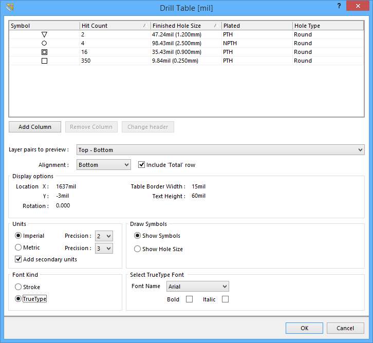
The Drill Table dialog
Summary
The Drill Table dialog is used to configure a Drill Table object. A drill table, also known as a drill drawing legend, is a standard element required for manufacture of a Printed Circuit Board. The drill table lists the size and number of holes for each drill used on the board. The drill table updates in real time meaning as hole-containing objects, such as pads and vias, are placed or removed from the PCB design, the table updates.
Access
The dialog can be accessed during placement:
- By pressing the Tab key.
After placement, the dialog can be accessed in the following ways:
- Double-click on the drill table object.
- Place the cursor over the object, right-click then choose Properties from the context menu.
Options/Controls
Grid Area
The drill table displays detailed information for each symbol type. It can be customized including:
- Changing the column order - Click on a column header then drag to change the order of columns.
- Change a column header - Select the column then click the Change header button or right-click in the column then select Change column header from the menu.
- Hide a column - Select the column then click the Remove Column button or right-click then select Remove column from the menu.
- Show a column - Click the Add Column button then select the required column or right-click then select the relevant Add column menu entry.
- Add a custom column - Click the Add Column button then select Custom column or right-click and select the Add column » Custom column menu entry. Both the header and the values are user-defined in a custom column.
Layer Pairs to Preview
The drill table supports multi-layer boards that use layer-pair drilling. To support you in using the drill table during the design process, the table includes the Layer pairs to preview option. Set this to restrict the table to only show the drill holes for just the selected layer-pair.
Alignment
The table can be built from the bottom-up, Alignment = Bottom, or from the top-down, Alignment = Top. Use this setting to allow for table size changes without impacting surrounding objects in the workspace.
Display Options
- Location X - Current X location of the drill table reference point. The reference point is the bottom left corner if Alignment = Bottom, or top left corner if Alignment = Top.
- Location Y - Current Y location of the drill table reference point. The reference point is the bottom left corner if Alignment = Bottom, or top left corner if Alignment = Top.
- Rotation - Angle in degrees that the the drill table is rotated.
- Table Border Width - Width of the lines used to create the table border.
- Text Height - Height of the text used in the drill table.
- Text Width - Stroke width of the text used in the drill table. This option is available only if the Font Kind is set to Stroke.
Units
- Imperial / Metric - Set the Units to be either Metric or Imperial.
- Precision - Set the required precision (number of digits after the decimal point) for each type of Units.
- Add secondary units - Enabling this displays each numerical value in both Unit types with the secondary units enclosed in brackets.
Draw Symbols
Each hole size can be represented by one of the following drawing symbols:
- Show Symbols - Draw a small geometric symbol at the location of each drill site. Note that a symbol is automatically chosen for each hole size, up to a total of 15 different sizes. These symbols tend to be open in their design. If a hole center marker is required, include the Drill Guide layer in the output generation. If required, each Symbol can be replaced by a letter. This is done in the PCB Hole Size Editor as described below.
- Show Hole Size - Draw the numerical size of the hole at the location of each drill site. Enable this option to show the hole size in drill table.
Font Kind
- Stroke - select to use Stroke fonts.
- TrueType - select to use fonts available on your PC (in the \Windows\Fonts folder). TrueType fonts offer full Unicode support.
Select TrueType Font
- Font Name - use this field to choose the required TrueType font. The drop-down list is populated with TrueType and OpenType (a superset of TrueType) fonts found in the \Windows\Fonts folder. Note, the list will only include entries for detected (and uniquely named) root fonts. For example, Arial and Arial Black will be listed but Arial Bold, Arial Bold Italic, etc., will not. Use the Bold and Italic options to add emphasis to the text.
- Bold - enable this option to make the dimension text bold.
- Italic - enable this option to make the dimension text italic.
Select Stroke Font
- Font Name - use the drop-down to select the desired Stroke font. Choices are:
- Default - a simple vector font designed for pen plotting and vector photo plotting.
- Sans Serif - a complex font that will slow down vector output generation, such as Gerber.
- Serif - a complex font that will slow down vector output generation, such as Gerber.