
Sheet Entry
Contents
Parent page: Schematic Objects
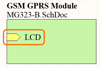
A placed Sheet Entry
Summary
A sheet entry is an electrical design primitive that belongs within a sheet symbol. It is placed within a sheet symbol to designate input/output ports for the symbol. The sheet entries correspond to ports placed in the source schematic sub-sheet that the symbol represents.
Availability
Sheet Entries are available for placement in the Schematic Editor only by clicking Home | Circuit Elements | ![]() from the main menus.
from the main menus.
Placement
After launching the command, the cursor will change to a cross-hair and you will enter sheet entry placement mode. Placement is made by performing the following sequence of actions:
- Move the sheet entry attached to the cursor over a placed sheet symbol on the sheet.
- Adjust the position of the sheet entry in relation to an edge of the sheet symbol, then click or press Enter to anchor the sheet entry to the required edge and complete placement.
- Continue placing further sheet entries, or right-click or press Esc to exit placement mode.
While the sheet entry is still floating on the cursor, and while it is within the bounds of a sheet symbol, press the Tab key to access an associated properties dialog, from where properties for the sheet entry can be changed on-the-fly.
Graphical Editing
This method of editing allows you to select a placed sheet entry object directly in the workspace and change its location graphically.
Sheet entries can only be adjusted with respect to their shape by changing their I/O Type (accessed through the Sheet Entry dialog). As such, editing handles are not available when the Sheet Entry object is selected.
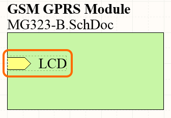
A selected Sheet Entry
- Click and drag to reposition the sheet entry within its parent sheet symbol as required.
- Hold Ctrl, then click and drag the sheet entry to move it from the current sheet symbol to another sheet symbol on the sheet. Once the sheet entry has cleared the boundary of the source sheet symbol, the Ctrl key can be released.
- Clicking and dragging the sheet entry outside of the sheet symbol boundary will cause the sheet symbol to automatically resize to accommodate the entry's new location.
- The name text for a sheet entry object can be edited in-place by:
- Single-clicking the sheet entry to select it.
- Single-clicking again (or pressing the Enter key) to enter the in-place editing mode. Sufficient time between each click should be given to ensure the software does not interpret the two single-clicks as one double-click (which would open the sheet entry's properties dialog).
- To finish editing in-place text, press the Enter key, or use the mouse to click away from the sheet entry.
Non-Graphical Editing
The following methods of non-graphical editing are available:
Via an Associated Properties Dialog
Dialog page: Sheet Entry
This method of editing uses the following dialog to modify the properties of a sheet entry object.
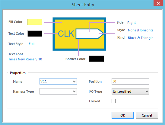
The Sheet Entry dialog
The dialog can be accessed during placement by pressing the Tab key (while the sheet entry is still floating on the cursor, and while it is within the bounds of a sheet symbol).
After placement, the dialog can be accessed in one of the following ways:
- Double-click on the placed sheet entry object.
- Place the cursor over the sheet entry object, right-click then choose Properties from the context menu.
Via the SCH Inspector Panel
Panel pages: SCH Inspector
The SCH Inspector panel enables you to interrogate and edit the properties of one or more design objects in the active document.
Sheet Entry Actions
Right-clicking over a placed sheet entry will pop-up a context-sensitive menu, from which the following commands are available (on the Sheet Entry Actions sub-menu) that act on that sheet entry (or all currently selected sheet entries, where applicable):
- Jump to Port <PortName> - use this command to jump to the sheet entry's corresponding port on the sub-sheet referenced by that entry's parent sheet symbol.
- Toggle Sheet Entry IO Type - use this command to toggle the I/O Type for the sheet entry.
Example of toggling sheet entry IO Type
The actual change depends on the current I/O Type as follows:
- Unspecified remains Unspecified
- Output changes to Input
- Input changes to Output
- Bidirectional remains Bidirectional.
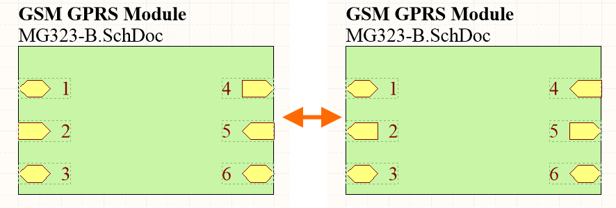
- Swap Sheet Entry Side - use this command to relocate the sheet entry to the directly opposite side of its parent sheet symbol. The sheet entry's I/O Type is not changed by the swap.

Example of swapping sheet entry side.
- Place Harness Connector of Type <HarnessConnectorType> - use this command to quickly place a harness connector (complete with respective defined harness entries) for connection to the sheet entry.
Notes
- When a Sheet Entry is connected to a Signal Harness, the Sheet Entry becomes a Harness object. By default, the Sheet Entry will change color to match the color of the Signal Harness. Disable the Sheet Entries and Ports use Harness Color option on the Schematic - Graphical Editing page of the Preferences dialog to specify your own color for Sheet Entries or to use the default color.
- When a Sheet Entry is connected to a Harness Connector by a Signal Harness, the Harness Type in the Sheet Entry dialog is automatically populated with the Harness Type of the Harness Connector. When a Sheet Entry is connected to a Port by a Signal Harness and the Port has a Harness Type declared, the Sheet Entry will become a Harness object and change to the color of the Signal Harness. If you move the Sheet Entry away from the Harness Connector and the Harness Type field is not populated, the Sheet Entry will revert back to the default color.
- If you need to negate (include a bar over the top of) a sheet entry name, this can be done by including a backslash character after each character in the name (e.g., E\N\A\B\L\E\).
- When instantiating multiple channels from the same sheet symbol, certain signals are repeated and sent individually to each instantiated channel. With respect to a sheet entry, a signal is repeated by using the Repeat keyword in the sheet entry's name (e.g., Repeat(Headphone)). The sheet entry is then wired to a bus, which, in turn, carries the individual signals to their corresponding instantiated destinations.