Polygon
Contents
Parent page: Schematic Objects
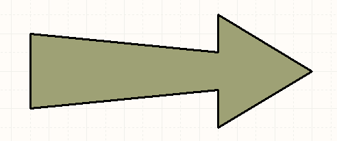
A placed Polygon
Summary
A polygon is a non-electrical drawing primitive. It is a multi-sided graphical object that can be placed on a schematic sheet. A polygon must have at least three sides and can be filled or unfilled.
Availability
Polygons can be placed in both the Schematic Editor and the Schematic Library Editor.
- Schematic Editor - click Home | Graphical Elements |
 from the main menus.
 - Schematic Library Editor - click Home | Place | from the main menus.
Placement
After launching the command, the cursor will change to a cross-hair and you will enter polygon placement mode. Placement is made by performing the following sequence of actions:
- Click or press Enter to anchor the starting point for the polygon.
- Position the cursor and click or press Enter to anchor a vertex, move the mouse and repeat as often as required to define the shape of the polygon.
- After placing the final vertex point, right-click or press Esc to complete placement of the polygon.
- Continue placing further polygons, or right-click or press Esc to exit placement mode.
Graphical Editing
This method of editing allows you to select a placed polygon object directly in the workspace and change its size and/or shape graphically.
When a polygon object is selected, an editing handle (vertex) will appear at each corner as shown in the image below.
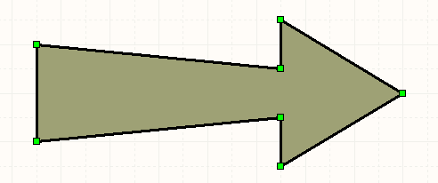
A selected Polygon
- Click and drag on a vertex to move that vertex.
- Ctrl+click and drag on an edge to move that edge of the polygon.
- Right-click on a vertex point then choose the Edit Polygon Vertex n command to access the Vertices tab of the Polygon dialog, with the entry for the
nthvertex selected ready for editing. - Ctrl+click and hold on an edge, then press Insert to add a vertex at that point.
- Click and hold on a vertex, then press Delete to remove that vertex.
Non-Graphical Editing
The following methods of non-graphical editing are available:
Via an Associated Properties Dialog
Dialog page: Polygon
This method of editing uses the Polygon dialog to modify the properties of a polygon object.
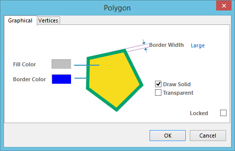
The Polygon dialog
The dialog can be accessed during placement by pressing the Tab key.
After placement, the dialog can be accessed in one of the following ways:
- Double-click on the placed polygon object.
- Place the cursor over the polygon object, right-click then choose Properties from the context menu.
Via an Inspector Panel
Panel pages: SCH Inspector, SCHLIB Inspector
An Inspector panel enables you to interrogate and edit the properties of one or more design objects in the active document.