
Manual Junction
Contents
Parent page: Schematic Objects

A Manual Junction is used to create a cross-over type connection on the schematic. Note that the color is different from a Compiler-generated Junction.
Summary
A junction is an electrical design primitive. It is a small circular object used to logically join intersecting wires, buses, or signal harnesses, on a schematic sheet. A manual junction allows you to create a connection between crossed wires/buses/signal harnesses by placing the junction at the crossing point. This is different from a Compiler-generated junction, which is automatically inserted when two wires/buses/signal harnesses are connected in a T-type fashion, or when a wire/bus/signal harness connects orthogonally to a pin or power port/bus power port.
Availability
Manual junctions are available for placement in the Schematic Editor only by clicking Home | Circuit Elements | ![]() from the main menus.
from the main menus.
Placement
After launching the command, the cursor will change to a cross-hair and you will enter junction placement mode.
- Click or press Enter to place a junction at the cursor position.
- Continue placing junctions or right-click or press Esc to exit placement mode.
Additional actions that can be performed during placement are:
- Press the Tab key to access an associated properties dialog, from where properties for the manual junction can be changed on-the-fly.
Graphical Editing
This method of editing allows you to select a placed manual junction object directly in the workspace and change its location graphically. Manual junctions can only be adjusted with respect to their size through the Junction dialog. As such, editing handles are not available when the manual junction object is selected:

A selected Manual Junction, ready to be moved, copied or deleted
Click anywhere inside the dashed selection box then drag to reposition the manual junction as required.
Non-Graphical Editing
The following methods of non-graphical editing are available:
Via an Associated Properties Dialog
Dialog page: Junction
This method of editing uses the Junction dialog to modify the properties of a manual junction object.
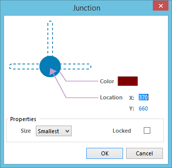
The Junction dialog
The dialog can be accessed during placement by pressing the Tab key.
After placement, the dialog can be accessed in one of the following ways:
- Double-click on the placed manual junction object.
- Place the cursor over the manual junction object, right-click then choose Properties from the context menu.
Displaying the Manual Junction Connection Status
Display of the connection status of manual junctions can be controlled on the Schematic - Compiler page of the Preferences dialog.

These options are used to highlight the connection status of Manual Junctions.
If the Display option is enabled, each manual junction that is creating a valid connection is back-colored in the color defined by the Color option. Note that the default Size of the Connection Status display feature is Smallest, which is the same size as the default manual junction size. This means the back-color will not be visible unless the Size is set to Small or larger as shown in the image below.
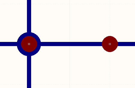
The brown Manual Junction on the left is creating a valid connection as indicated by the blue back-color behind it.
Via the SCH Inspector Panel
Panel page: SCH Inspector
The SCH Inspector panel enables you to interrogate and edit the properties of one or more design objects in the active document.