
Break Wire Properties
Other Related Resources
Parent page: Sch Dialogs
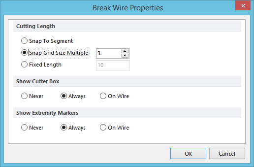
The Break Wire Properties dialog
Summary
This dialog provides controls to specify the behavior of the cutting tool when using the Break Wire feature.
Access
From the Schematic Editor, enter Break Wire mode (Tools | Convert | ![]() ) then press the Tab key.
) then press the Tab key.
Options/Controls
- Cutting Length - the following options are available for controlling the length of wire that gets cut:
- Snap To Segment - choose this option to have the cutter snap to an entire wire segment.
- Snap Grid Size Multiple - choose this option to have the cutter sized to a defined multiple of the current snap grid. Enter a value for the multiplier between 2 and 10 (inclusive) in the field to the right.
- Fixed Length - choose this option to create a fixed-length cutter, the length of which is specified by entering a value in the field to the right.
- Show Cutter Box - the following options are available for controlling the display of the cutter box (dotted rectangular box) while in Break Wire mode:
- Never - never display the cutter box.
- Always - always display the cutter box regardless of whether the cursor is over a wire segment or not.
- On Wire - only display the cutter box when the cursor passes over a wire segment.
- Show Extremity Markers - the following options are available for controlling the display of extremity markers (at the ends of the cutter box) while in Break Wire mode:
- Never - never display the extremity markers.
- Always - always display the extremity markers regardless of whether the cursor is over a wire segment or not.
- On Wire - only display the extremity markers when the cursor passes over a wire segment.
Notes
- Cutting Length options for the Break Wire tool can also be defined on the Schematic - Graphical Editing page of the Preferences dialog. Values modified for length options at the local document level (through the Break Wire Properties dialog) will be instantly reflected back at the preferences level.