
Signal Harness
Parent page: Sch Dialogs
The Signal Harness dialog
Summary
This dialog provides controls to specify the properties of a Signal Harness object. A Signal Harness is an electrical design primitive. It is an abstract connection that enables the logical grouping of different signals including buses, wires and other signal harnesses for increased flexibility and streamlined design. Signal Harnesses allow for the creation and manipulation of higher level abstract connections between subcircuits in your PCB Projects. They allow for a more complex design within the same schematic workspace, increasing readability of designs and building potential for re-use.
Access
The Signal Harness dialog can be accessed during placement by pressing the Tab key.
After placement, the dialog can be accessed in one of the following ways:
- Double-click on the placed signal harness object.
- Place the cursor over the signal harness object, right-click then choose Properties from the context menu.
Options/Controls
Graphical Tab
Use the dialog's Graphical tab to modify graphical properties of the signal harness object.
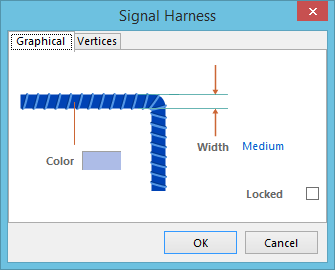
Signal Harness dialog - Graphical tab
- Width - the width of the signal harness line. Available widths are:
Smallest,Small,Medium, andLarge. - Color - click the color sample to change the color of the signal harness using the standard Choose Color dialog.
- Locked - enable this option to protect the signal harness from being edited graphically.
Vertices Tab
Use the dialog's Vertices tab to edit the individual vertices of the currently selected signal harness object. You can also add new vertices to the signal harness, or remove selected vertices altogether.
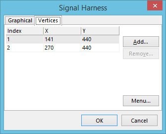
Signal Harness dialog - Vertices tab
- Vertices Grid - the main region lists all of the vertex points currently defined for the signal harness in terms of:
- Index - the assigned index of the vertex.
- X - the X (horizontal) coordinate for the vertex.
- Y - the Y (vertical) coordinate for the vertex.
- Add - click this button to add a new vertex point. The new vertex will be added below the currently focused vertex entry and will initially have the same coordinates as the focused entry
- Remove - click this button to remove the currently selected vertex entry(ies) in the list. This command will be unavailable if there are only two vertices present for the signal harness.
- Menu - click this button to access a menu containing the following commands:
- Edit - right-click on a coordinate cell (X or Y) for a vertex then use this command to edit the value in that cell. Alternatively, click directly on the cell.
- Add - use this command to add a new vertex point. The new vertex will be added below the currently focused vertex entry and will initially have the same coordinates as the focused entry.
- Remove - use this command to remove the currently selected vertex entry(ies) in the list. This command will be unavailable if there are only two vertices present for the signal harness.
- Copy - use this command to copy the content of the selected cells in the list to the clipboard (alternatively use Ctrl+C).
- Paste - use this command to paste the content of the clipboard into the list starting at the selected cell (alternatively use Ctrl+V).
- Select All - use this command to quickly select the entire grid contents of the list.
- Select Column - use this command to quickly select the entire column in which the currently focused cell resides.
- Move Up - use this command to move the selected vertex upward in the list.
- Move Down - use this command to move the selected vertex downward in the list.
- Move Signal Harness By XY - use this command to move the entire signal harness object. The Move Signal Harness By dialog will open in which you can enter the increment value to be applied to each vertex point's X and Y coordinates.