
Sheet Entry
Parent page: Sch Dialogs
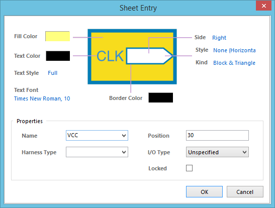
The Sheet Entry dialog
Summary
This dialog provides controls to specify the properties of a Sheet Entry object. A sheet entry is an electrical design primitive that belongs within a sheet symbol. It is placed within a sheet symbol to designate input/output ports for the symbol. The sheet entries correspond to ports placed in the source schematic sub-sheet that the symbol represents.
Access
The Sheet Entry dialog can be accessed during placement by pressing the Tab key (while the sheet entry is still floating on the cursor, and while it is within the bounds of a sheet symbol).
After placement, the dialog can be accessed in one of the following ways:
- Double-click on the placed sheet entry object.
- Place the cursor over the sheet entry object, right-click then choose Properties from the context menu.
Options/Controls
- Fill Color - click the color sample to change the fill color for the sheet entry using the standard Choose Color dialog.
- Text Color - click the color sample to change the text color for the sheet entry using the standard Choose Color dialog.
- Side - use this field to specify where the sheet entry is positioned in relation to the parent sheet symbol. Available options are: Left, Right, Top, and Bottom.
- Style - use this field to manually control the style of the sheet entry when the I/O Type is set to Unspecified. The style is essentially the direction in which the entry 'points'. Available options are: None (Horizontal), Left, Right, Left & Right, None (Vertical), Top, Bottom, Top & Bottom.
- Kind - use this field to control the graphical arrow style for the sheet entry. Available options are: Block & Triangle, Triangle, Arrow, and Arrow Tail.
- Text Style - use this field to determine how the text for the sheet entry is displayed when bus syntax is used. Choose from the following options:
- Full - choose this option to display the net identifier information in full. For example, the N[0..7] net identifier string will be shown as N[0..7].
- Prefix - choose this option to display only the prefix of the net identifier, ignoring the bracketed portion. For example, the N[0..7] net identifier string will be shown as N.
- Text Font - this control serves two purposes. First, it reflects the currently chosen font for the text in terms of Font Name, Font Size and Font Style. Second, when clicked it provides access to the standard Font dialog in which you can change the font as required.
- Border Color - click the color sample to change the outline color for the sheet entry using the standard Choose Color dialog.
Properties
- Name - the current name of the sheet entry. The entry in this field defines the connectivity of the sheet entry. A sheet entry connects electrically to a port on the sub-sheet below with the same name. Enter the name directly or use the field's drop-down list to choose a name from all existing port names on the sub-sheet referenced by the parent sheet symbol.
- Position - the current position of the sheet entry in relation to the top edge of the sheet symbol (when placed along the left or right edges), or left edge of the sheet symbol (when placed along the top or bottom edges). Enter a greater value to move the sheet entry further down, or right, respectively.
- Harness Type - this field is used to provide the connectivity between the sheet entry and a defined signal harness system, allowing a collection of signals to be transferred between sheets in the design hierarchy. The Harness Type itself is defined either manually in the associated Harness Definition File or as part of the properties of a Harness Connector. The associated drop-down lists all currently defined Harness Types detected across the source schematic documents of the active project.
- I/O Type - defines the electrical properties of the sheet entry. Select an option from the drop-down. Available options are: Unspecified, Output, Input, and Bidirectional.
- Locked - enable this option to protect the sheet entry from being edited graphically.