
PolyLine
Parent page: Sch Dialogs
The PolyLine dialog
Summary
This dialog provides controls to specify the properties of a Polyline (Line) object. A line is a non-electrical polyline drawing primitive. Lines are used for adding reference information to a document, such as building graphical symbols, custom sheet borders and title blocks, and annotating the schematic.
Access
The PolyLine dialog can be accessed during placement by pressing the Tab key.
After placement, the dialog can be accessed in one of the following ways:
- Double-click on the placed line object.
- Place the cursor over the line object, right-click then choose Properties from the context menu.
Graphical Tab
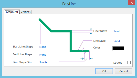
PolyLine dialog - Graphical tab
Use the dialog's Graphical tab to modify graphical properties of the polyline object.
Options/Controls
- Line Width - the width of the line. Available widths are:
Smallest,Small,Medium, andLarge. - Line Style - the style in which the line is drawn. Options are Solid, Dashed, Dotted, and Dash Dotted.
- Color - click the color sample to change the color of the line using the standard Choose Color dialog.
- Start Line Shape - use this field to specify whether or not the starting point of the line is to have a particular shape and what that shape should be. Available options are: None, Arrow, SolidArrow, Tail, SolidTail, Circle, Square.
- End Line Shape - use this field to specify whether or not the end point of the line is to have a particular shape and what that shape should be. Available options are: None, Arrow, SolidArrow, Tail, SolidTail, Circle, Square.
- Line Shape Size - use this field to determine the size of the shape used at the start and/or end points of the line if shapes have been specified for use. Available sizes are:
Smallest,Small,Medium, andLarge. - Locked - enable this option to protect the line from being edited graphically.
Vertices Tab
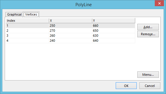
PolyLine dialog - Vertices tab
Use the dialog's Vertices tab to edit the individual vertices of the currently selected line object. You can also add new vertices to the line or remove selected vertices altogether.
Options/Controls
- Vertices Grid - the main region of the tab lists all of the vertex points currently defined for the line in terms of:
- Index - the assigned index of the vertex.
- X - the X (horizontal) coordinate for the vertex.
- Y - the Y (vertical) coordinate for the vertex.
- Add - click this button to add a new vertex point. The new vertex will be added below the currently focused vertex entry (as distinguished by a dotted outline around a cell in its row) and will initially have the same coordinates as the focused entry.
- Remove - click this button to remove the currently selected vertex entries in the list. This command will be unavailable if there are only two vertices present for the line.
- Menu - click this button to access a pop-up menu containing the following commands:
- Edit - right-click on a coordinate cell (X or Y) for a vertex then use this command to edit the value in that cell. Alternatively, click directly on the cell.
- Add - use this command to add a new vertex point. The new vertex will be added below the currently focused vertex entry (as distinguished by a dotted outline around a cell in its row) and will initially have the same coordinates as the focused entry.
- Remove - use this command to remove the currently selected vertex entries in the list. This command will be unavailable if there are only two vertices present for the line.
- Copy - use this command to copy the content of the selected cells in the list to the clipboard (alternatively use Ctrl+C).
- Paste - use this command to paste the content of the clipboard into the list starting at the selected cell (alternatively use Ctrl+V).
- Select All - use this command to quickly select the entire grid contents of the list.
- Select Column - use this command to quickly select the entire column in which the currently focused cell resides.
- Move Up - use this command to move the selected vertex upward in the list.
- Move Down - use this command to move the selected vertex downward in the list.
- Move Line By XY - use this command to move the entire line object. The Move Line By dialog will open in which you can enter the increment value to be applied to each vertex point's X and Y coordinates.