
Note
Other Related Resources
Parent page: Sch Dialogs
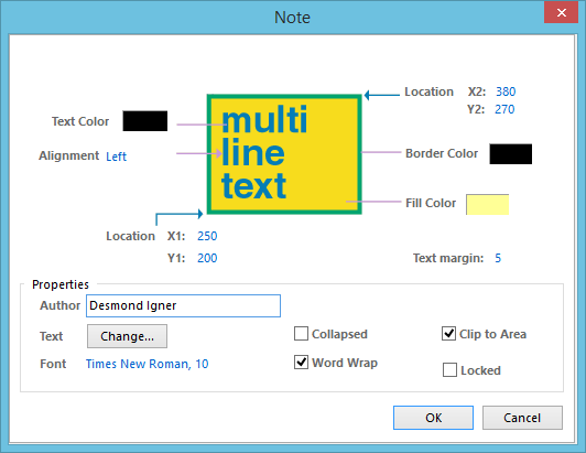
The Note dialog
Summary
This dialog provides controls to specify the properties of a Note object. A note is a non-electrical drawing primitive. It is used to add informative or instructional text to a specific area within a schematic, similar to that of commenting a program's source code. The note is a resizeable rectangular area that can contain multiple lines of text and can automatically wrap and clip text to keep it within the bounds of the note.
Access
The Note dialog can be accessed during placement by pressing the Tab key.
After placement, the dialog can be accessed in one of the following ways:
- Double-click on the placed note object.
- Place the cursor over the note object, right-click then choose Properties from the context menu.
Options/Controls
- Text Color - click the color sample to change the color used for the actual text entered into the note using the standard Choose Color dialog.
- Alignment - specifies the alignment of the text contained within the note. Choose from Center, Left, and Right alignment.
- Location X1/Y1 - the current X (horizontal) and Y (vertical) coordinates for the bottom-left corner of the note. Edit these values to change the position of this corner in the horizontal and/or vertical planes, respectively.
- Location X2/Y2 - the current X (horizontal) and Y (vertical) coordinates for the top-right corner of the note. Edit these values to change the position of this corner in the horizontal and/or vertical planes, respectively.
- Border Color - click the color sample to change the color used for the border around the note using the standard Choose Color dialog.
- Fill Color - click the color sample to change the fill color for the note using the standard Choose Color dialog.
- Text margin - the amount of space (padding) between the text and the note border. The value specified applies equally to Left, Top, Right and Bottom margins for the note.
Properties
- Author - use this field to enter the name of the person writing the note.
- Text - click the Change button associated with this field to access the Note Text dialog in which text for the note can be entered, as required.
- Font - this control serves two purposes. First, it reflects the currently chosen font applied to the text entered within the note in terms of Font Name, Font Size and Font Style. Second, when clicked it provides access to the standard Font dialog in which you can change the font as required.
- Collapsed - enable this option to display the note in collapsed (small triangle) mode. Disable this option to display the note in expanded (full frame) mode.
- Word Wrap - enable this option to have the text within the note area automatically wrap to fit the width of the note.
- Clip to Area - this option comes into play if word wrapping is disabled. With this option enabled, text will be kept within the bounds of the note. When disabled, text will spill out of the note onto the schematic sheet.
- Locked - enable this option to protect the note from being edited graphically.