Text
Contents
Parent page: PCB Objects

A placed Text object
Summary
Text, also referred to as a String, is a primitive design object. It places text on the selected layer in a variety of display styles. As well as user-defined text, a special type of text referred to as a special string, can be used to display board or system information or the value of user-parameters, on the board.
Availability
Text objects are available for placement in both PCB and PCB Library Editors by clicking Home | Place | ![]() from the main menus.
from the main menus.
Placement
After launching the command, the cursor will change to a cross-hair and you will enter text placement mode. A text object will appear "floating" on the cursor:
- Position the cursor then click or press Enter to place the text object.
- Continue placing further text objects, or right-click or press Esc to exit placement mode.
Additional actions that can be performed during placement are:
- Press the Spacebar to rotate the text object counterclockwise or Shift+Spacebar for clockwise rotation. Rotation is in accordance with the value for the Rotation Step defined on the PCB Editor – General page of the Preferences dialog.
- Press the X or Y keys to mirror the text object along the X-axis or Y-axis respectively.
- Press the L key to flip the text object to the other side of the board.
- Press the + and - keys (on the numeric keypad) to cycle forward and backward through all visible layers in the design respectively – to change placement layer quickly.
- Press the Tab key to access an associated properties dialog, from where properties for the object can be changed on-the-fly.
Graphical Editing
This method of editing allows you to select a placed text object directly in the workspace and change its location, rotation, orientation, or in the case of inverted strings, its size.
When a non-inverted text object is selected, the following editing handle is available:
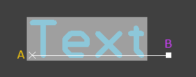
A selected Text object (non-inverted).
- Click and drag B to rotate the text about point A.
- Click anywhere on the text– away from any editing handles – and drag to reposition it. The text will be held by point A and can be rotated (Spacebar/Shift+Spacebar) or mirrored (X or Y keys to mirror along the X-axis or Y-axis respectively).
When an inverted text object with an editable bounding rectangle (inverted rectangle) is selected, the following editing handles are available:
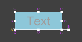
A selected String (inverted, and using an inverted rectangle).
- Click and drag B to rotate the text about point A.
- Click and drag C to resize the rectangle in the vertical and horizontal directions simultaneously.
- Click and drag D to resize the rectangle in the vertical and horizontal directions separately.
- Click anywhere on the text – away from any editing handles – and drag to reposition it. The text will be held by point A and can be rotated (Spacebar/Shift+Spacebar) or mirrored (X or Y keys to mirror along the X-axis or Y-axis respectively).
Non-Graphical Editing
The following methods of non-graphical editing are available:
Editing via an Associated Properties Dialog
Dialog page: Text
This method of editing uses the following dialog to modify the properties of a text object.

The Text dialog
The Text dialog can be accessed during placement by pressing the Tab key.
After placement, the dialog can be accessed in one of the following ways:
- Double-click on the placed text object.
- Place the cursor over the text object, right-click then choose Properties from the context menu.
Editing via an Inspector Panel
Panel pages: PCB Inspector, PCBLIB Inspector
An Inspector panel enables you to interrogate and edit the properties of one or more design objects in the active document. Used in conjunction with appropriate filtering, the panel can be used to make changes to multiple objects of the same kind, from one convenient location.
Special Strings
While text objects can be used to place user-defined text on the current PCB layer, it is not just user-defined text that can be placed. To assist in producing documentation, the concept of "special strings" is used. These act as placeholders for design, system or user information that is to be displayed on the PCB at the time of output generation.

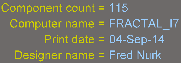
Examples of design, system and design parameter special strings, shown as source strings on the left, and converted on the right.
There is a default set of predefined special strings provided for use with new PCB documents. You can also add your own custom special strings by defining additional parameters at the project-level. These parameters are defined on the Parameters tab of the Options for Project dialog.
Placing a Special String
To use a special string on a PCB, place a string object and select one of the special string names from the drop-down.
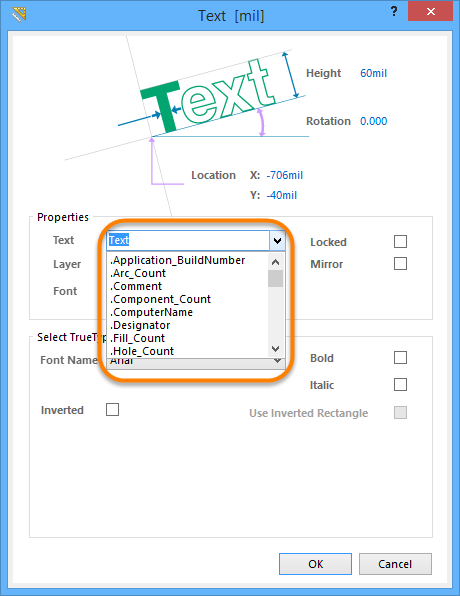
Accessing special strings for a placed text object.
Revealing Special Strings in the Workspace
The values of some special strings can only be viewed when the relevant output is generated. Most special strings can be viewed directly on-screen, however, by enabling the Convert Special Strings option on the View Options page of the View Configurations dialog when viewing the board in 2D (press the L shortcut to open the dialog).
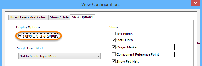
Enabling the Convert Special Strings option allows the data for most of the special strings to be viewed in the workspace
prior to output generation.
PCB Predefined Special Strings
The following are the predefined, system-based special strings available for use on a PCB document:
.Application_BuildNumber– the version of the software in which the PCB is currently loaded. When generating Gerber output, use this string to record the software build on which the design was created..Arc_Count– the number of arcs on the PCB..Comment– the comment string for a component (placed on any layer in the library editor as part of the component footprint)..Component_Count– the number of components on the PCB..ComputerName– the name of the computer on which the software is installed and running..Designator– the designator string for a component (placed on any layer in the library editor as part of the component footprint)..Fill_Count– the number of fills on the PCB..Hole_Count– the number of drill holes on the PCB..Item– the Item to which the generated data relates (e.g.,D-810-2000). The data will be used to build that Item..ItemAndRevision– the Item and specific revision of that Item to which the generated data relates in the format<Item ID>-<Revision ID>(e.g.,D-810-2000-01.A.1). The data will be used to build that specific revision of that particular Item..ItemRevision– the specific revision of the Item to which the generated data relates (e.g., 01.A.1). The data is stored in that Item Revision within the target Altium Vault..ItemRevisionBase– the Base Level portion of an Item Revision's naming scheme (e.g., 1)..ItemRevisionLevel1– the Level 1 portion of an Item Revision's naming scheme (e.g., A)..ItemRevisionLevel1AndBase– the Level 1 and Base Level portions of an Item Revision's naming scheme (e.g., A.1)..ItemRevisionLevel2– the Level 2 portion of an Item Revision's naming scheme (e.g., 01)..ItemRevisionLevel2AndLevel1– the Level 2 and Level 1 portions of an Item Revision's naming scheme (e.g., 01.A)..Layer_Name– the name of the layer on which the string is placed..Legend– a symbol legend for mechanical drill plots. This string is only valid when placed on the Drill Drawing layer. Note: this is a legacy feature; place a Drill Table object for more detailed drill information..Net_Count– the total number of different nets on the PCB..Net_Names_On_Layer– the names of all nets on the specific layer. This string is only valid when placed on an internal plane layer..Pad_Count– the number of pads on the PCB..Pattern– the names of the component footprints used on the PCB..Pcb_File_Name– the path and file name of the PCB document..Pcb_File_Name_No_Path– the file name of the PCB document..PCBConfigurationName– the name of the configuration from which the output has been generated..Plot_File_Name– for generated Gerber output, this string identifies the file name of the Gerber plot file. For printed output, it identifies the layer depicted within the output. For ODB++ output, it identifies the name of the parent folder in which the files are stored..Poly_Count– the number of polygons on the PCB (consisting of polygon pours, internal planes and split planes)..Print_Date– the date of printing/plotting..Print_Scale– the printing/plot scale factor..Print_Time– the time of printing/plotting..Printout_Name– the name of the printout..SlotHole_Count– the number of slotted holes on the PCB..SquareHole_Count– the number of square holes on the PCB..String_Count– the number of strings on the PCB..Track_Count– the number of tracks on the PCB.- .VariantName - the variant of the design from which the output has been created.
.VersionControl_RevNumber– the current revision number of the document. Version control must be used for this string to contain any information..Via_Count– the number of vias on the PCB.
TrueType Fonts
When using TrueType fonts, TrueType and OpenType (a superset of TrueType), fonts found in the \Windows\Fonts folder will be available for use. The feature also offers full Unicode support.
To use a TrueType font, choose a font type from the drop-down field in the Select TrueType Font region. Use the Bold and/or Italic options to add emphasis to the text as required.
Additional options for TrueType fonts are available. Enable the Inverted option to display the text as inverted, with control over the size of the border around the text.

An example of inverted TrueType text.
The Use Inverted Rectangle option extends the control over the bounding rectangle of the inverted text, including: rectangle size, text justification within the rectangle, and an offset for the text in relation to the rectangle's edge.
Fine-tune the appearance of inverted text with control over the bounding rectangle, and the location of the text within it.