Board Shape
Contents
Parent page: PCB Objects

The Board Shape defines the shape of the finished board.
Summary
The board shape, also referred to as the board outline, is a closed polygon that defines the boundary, or extents, of the board. As well as providing a visual guideline of the extents of the space available for the placement and routing of the design, the board shape is also used by the internal power planes as the reference for the power plane edge pullback and the edge for splitting power planes.
Availability
The board shape is available only in the PCB editor. When a new PCB file is created it opens with a default board shape.
There are three ways this shape can be altered. Commands for managing the Board Shape are accessed by clicking the Home | Board | ![]() button on the main menus. The commands available are:
button on the main menus. The commands available are:
- Redefine Board Shape - use this command to interactively draw a new shape.
- Move Board Shape - use this command to move the location of the board shape within the workspace.
- Edit Board Shape - use this command to interactively modify the shape of the board by moving vertices or sliding the edges of the shape.
- Define From Selected Objects - select a set of line and/or arc primitives that define a closed shape then use this command to redefine the board shape to match this shape.
- Create Primitives From Board Shape - use this command when the board shape exists but there are currently no objects along the boundary.
- Auto-Position Sheet - use this command to automatically resize the displayed PCB Sheet to exactly enclose the objects on mechanical layers linked to that sheet (will require a refresh of the workspace).
Redefining the Board Shape
After launching the Redefine Board Shape command, the cursor will change to a crosshair and you will enter the standard polygonal object placement mode. Board shape definition is made by performing the following sequence of actions:
- Position the cursor and click to anchor the starting vertex for the board shape.
- Move the cursor ready to place the second vertex. The default behavior is to place two edges with each click, with a user-defined corner shape between them. Refer to the Placement Modes section below for more details on changing corner modes.
- Continue to move the mouse and click to place further vertices.
- After placing the final vertex, right-click or press Esc to close and complete the definition of the board shape. There is no need to manually close the board shape since the software will automatically complete the shape by connecting the start point to the final point placed.
Placement Modes
When redefining the board shape there are five available corner modes, four of which also have corner direction sub-modes. During redefinition:
- Press Shift+Spacebar to cycle through the five available corner modes: 45 degree, 45 degree with arc, 90 degree, 90 degree with arc, and Any Angle.
- Press Spacebar to toggle between the two corner direction sub-modes.
- When in either of the arc corner modes, hold the
 or keys to shrink or grow the arc. Hold the Shift key as you press to accelerate arc resizing.
 - Press the 1 shortcut key to toggle between placing two edges per click, or one edge per click. In this second mode the dashed edge is referred to as the look-ahead segment (as shown in the last image in the set below).
- Press the Backspace key to remove the last vertex.
Press Shift+Spacebar to cycle through the five available corner modes, press the 1 shortcut to toggle placement between two edges or one edge.
Graphically Editing the Board Shape
After launching the Edit Board Shape command, the existing board shape will turn green. The outer shape of the shape is defined by a series of edges, where each edge is represented by an end vertex at each end, shown as a solid white square, and a center vertex in the middle, shown as a hollow white square. Each end vertex represents the location where two edges meet.
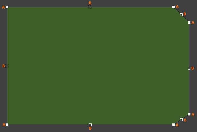
Editing handles for an example board shape after entering edit mode.
- Click and drag A to move the applicable end vertex.
- Click and drag B to move the applicable center vertex, effectively creating a new end vertex and splitting the original edge into two.
- Click anywhere along an edge, away from editing handles, and drag to slide that edge.
- Ctrl+click anywhere along an edge, away from editing handles, to insert a new end vertex.
- Click and hold on an end vertex then press Delete to remove that vertex.
Graphically Moving the Board Shape
After launching the Move Board Shape command, the existing board shape will turn green and an outline copy of the shape will be attached to the cursor. Move the shape to the desired new location within the workspace and click to effect placement. While moving, the board shape can be rotated or mirrored:
- Press the Spacebar to rotate the board shape counterclockwise or Shift+Spacebar for clockwise rotation. The Rotation Step size is defined on the PCB Editor – General page of the Preferences dialog.
- Press the X or Y keys to mirror the board shape along the X-axis or Y-axis respectively.

An outline copy of the board shape attaches to the cursor, while the original shape can be used
as a reference.
Cutting a Hole in the Board Shape
A board cutout can be placed anywhere in the board shape. To place a cutout, click Home | Board | ![]() . Note that the cutout is actually a Solid Region object configured to be a negative object. To learn more about placing this type of object, refer to the Region object.
. Note that the cutout is actually a Solid Region object configured to be a negative object. To learn more about placing this type of object, refer to the Region object.

A Board Cutout has been placed on the Board Shape.
Using PCB Sheets
The PCB Sheet is a special drawing feature used to represent the printed page in 2D Layout Mode. The sheet is not a design object, it is a display feature designed to work with objects placed on a mechanical layer. In the image below, dimension objects have been placed on a mechanical layer, and the sheet has been linked to this layer in the View Configurations dialog. Because it is linked and the Auto-size to linked layer option is enabled (Board Options dialog), the Home | Board | ![]() » Auto-Position Sheet command can be used to automatically resize the Sheet to exactly enclose the objects on that mechanical layer. This gives a professional, print-ready presentation of the board.
» Auto-Position Sheet command can be used to automatically resize the Sheet to exactly enclose the objects on that mechanical layer. This gives a professional, print-ready presentation of the board.
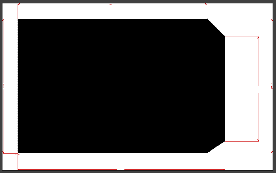
The sheet has been linked to the contents of the mechanical layer upon which the dimension objects have been placed,
resulting in a professional, print-ready presentation of the design.
Controlling the Display of the Sheet
To make the sheet visible in the PCB Editor:
- Click Home | Board | to open the Board Options dialog, then enable the Display Sheet option in the Sheet Position region. The sheet can be hidden at any time by disabling the Display Sheet option. All linked mechanical layers will also be hidden.
- The color of the sheet can be changed on the Board Layers And Colors tab of the View Configurations dialog. Select a new color for the Sheet Area Color and Sheet Line Color in the System Colors region of the tab.
Keepouts
As well as the board shape, you should also define a placement and routing boundary around the edge of the board. This is done by placing objects on the keepout layer. Objects placed on this layer define a no-crossing-allowed boundary for components and routing. Typically you want objects such as components and routing to be a certain distance from the edge of the board. This distance can be controlled by setting the applicable routing and component placement design rules. You can also define other routing and component keepouts areas for mechanical objects such as screw heads or other mounting requirements.
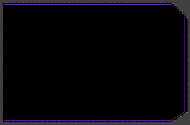
A keepout boundary defined by placing standard line objects on the keepout layer.
You can also define layer-specific keepouts on any copper layer. To do this:
- Click on the layer tab of the required layer.
- Define the boundary or area of the keepout area by placing layer-specific keepout objects (Home | Place | submenu). Layer specific keepouts are standard objects with the Keepout attribute enabled. They are displayed in the same color as the layer, with a keepout colored edge. Note that layer-specific keepout objects are not included in the Gerber or ODB++ output files.
Notes
- The board shape is not used for output generation; it is only the placed objects that are used.