Physical Materials
Related Pages
Parent page: PCB Dialogs
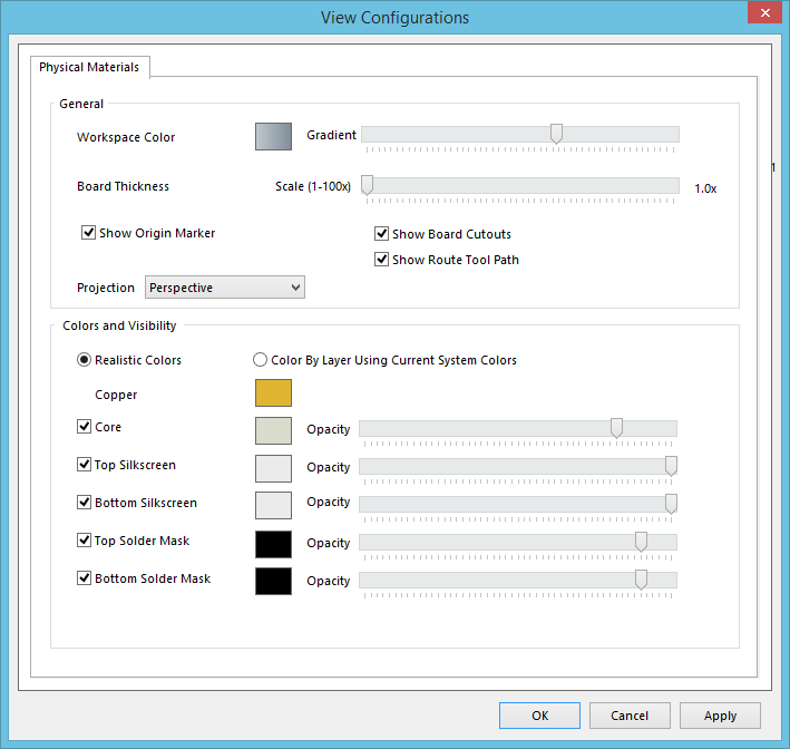
The Physical Materials tab of the View Configurations dialog
Summary
This tab of the View Configurations dialog provides controls to configure how the board is rendered in 3D.
Access
This is the only tab available for a 3D view configuration – accessed from within the View Configurations dialog. This dialog can be accessed from both the PCB Editor and the PCB Library Editor in the following ways:
- In 3D Layout Mode, click View | View |
 » View Configurations » View Configuration from the main menus.
 - Press the L key.
Options/Controls
General
- Workspace Color - reflects the color used for the 3D background workspace. Click the color swatch to change the color as required through the Choose Color dialog.
- Gradient - controls the color transition and direction of the 3D background workspace color. Placing the slide control in the center will stop any color transition and leave the background an even color.
- Board Thickness - controls the vertical scale of the 3D view to make it easier to differentiate layers when viewing the PCB internally. Drag the slider to the right to select between
1and100times the vertical scaling. The number displayed on the right of the slider control represents the current scale being used. For example, a value of10.0xwould show the board ten times its actual height.
- Show Origin Marker - enable to display an origin marker when in 3D display mode. This marker represents the
0,0,0position for the X, Y and Z-axes. - Show Board Cutouts - enable to show any board cutouts in the 3D workspace.
- Show Route Tool Path - enable to show the route tool path in the 3D workspace.
- Projection – determine the projection of the 3D view. Choose from:
- Perspective - choose this option for a more realistic 3D view of the PCB.
- Orthographic - choose this option to see the exact position of objects and text on the PCB without being obscured by surrounding objects.
Colors and Visibility
Choose the source for coloring of the various enabled (visible) layers, and objects within, for a 3D board:
- Realistic Colors - renders objects using more realistic, real-world coloring. A default set of colors will be loaded and presented to the right of each layer/object in the tab. With this option enabled, you can change the colors as required (using the respective color swatch).
- Color By Layer Using Current System Colors - renders objects using the default 2D layer colors. The set of colors will be loaded and presented to the right of each layer/object in the tab. You cannot change these colors.
- Copper is always visible for a board viewed in 3D.
Choose which of the additional layers to make visible:
- Core - enable to show the PCB core as part of the 3D model. The core represents the physical dielectric and prepreg layers of the PCB wafer.
- Top Silkscreen - enable to show the top silkscreen as part of the 3D view of the board. The silkscreens show printed information on the top and bottom of the PCB wafer, such as manufacturing information, component designators and outlines.
- Bottom Silkscreen - enable to show the bottom silkscreen as part of the 3D view of the board.
- Top Solder Mask - enable to show the top solder mask as part of the 3D view of the board. The solder masks represent photo or silkscreen areas on the board that have no copper, i.e. areas that are not used for electrically connecting components to the PCB.
- Bottom Solder Mask - enable to show the bottom solder mask as part of the 3D view of the board.
- Layer Color - when using Realistic Colors, you can change the colors as required. Click on the color swatch to the right of any of the above entries (including Copper) and change the color using the standard Choose Color dialog.
- Opacity - use the slide control, associated to each of the options above (excluding Copper), to alter the opacity of the layer. The greater the opacity, the less 'light' passes through the surface. Move the slider bar to the right for greater opacity.