
Fill
Other Related Resources
Parent page: PCB Dialogs
The Fill dialog
Summary
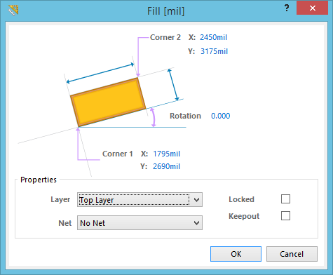
This dialog provides controls to modify the attributes of a Fill object. A fill is a rectangular primitive design object that can be placed on any layer for any design task requiring a rectangular shape.
Access
During placement, the dialog can be accessed by pressing the Tab key.
After placement, the dialog can be accessed in the following ways:
- Double-click on the placed dimension object.
- Place the cursor over the object, right-click then choose Properties from the context menu.
Options/Controls
- Corner 1 X/Y - Defines the location of the bottom left corner of the Fill in an un-rotated state.
- Corner 2 X/Y - Defines the location of the top right corner of the Fill in an un-rotated state.
- Rotation - Angle that the fill has been rotated. The fill is rotated around the geometric center. Note that when a fill is rotated, the Corner 1 and Corner 2 values are not changed. The minimum angular resolution is 0.001 degrees.
Properties
- Layer - The layer on which the fill is placed. Fills can be placed on any layer other than the system layers.
- Net - If the fill is a copper object, choose a Net for the Fill. All Nets in the current project will be listed in the drop-down list.
- Locked - Lock the object so that the object cannot be selected or edited graphically.
-
Keepout - Check this box to set the object as Keepout. A keepout object is used on a signal layer to create a layer-specific keepout. Layer-specific keepouts are not included during output generation.