
Designator
Other Related Resources
Parent page: PCB Dialogs
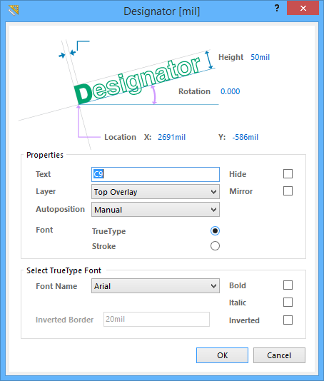
The Designator dialog
Summary
The Designator dialog provides controls to specify the properties of a component's Designator string independently of the component itself.
Access
Provided the target component designator string is visible in the workspace, the Designator dialog can be accessed in one of the following ways:
- Double-click on the designator string.
- Place the cursor over the designator string, right-click then choose Properties from the context menu.
Options/Controls
- Width - the current text stroke width (the "thickness" of the lines used to produce the lettering).
- Height - the current height of the text characters. The character width used to display or print the text is automatically proportioned to this height. A minimum height of 36mil (0.9mm) will allow the string to be legibly photoplotted.
- Rotation - the angle of alignment of the designator string measured counterclockwise in degrees from the horizontal.
- Location X/Y - the current X (horizontal) and Y (vertical) coordinates for the bottom-left handle of the designator string (the point by which it is held by the cursor when moving). Edit these values to change the position of the designator string in the horizontal and/or vertical planes.
Properties
- Text - use this field to directly enter the required text for the designator.
- Hide - enable this option to have the designator string hidden from the workspace.
- Layer - the layer to which the designator string is currently assigned. Designator strings can be assigned to any available layer. Click on the list to view and select a different layer from those currently defined for the board.
- Mirror - enable this option to flip the designator string across an axis that depends on the string's current Rotation and Location X/Y.
- Autoposition - the current positional style for the designator text in relation to its parent component. Choose a style other than Manual to have the text remain in that chosen position as the component is moved and rotated. To freely position the designator text and have it follow the parent component's movement/orientation, choose the Manual style. The following positional styles are available:
- Manual
- Left-Above
- Left-Center
- Left-Below
- Center-Above
- Center
- Center-Below
- Right-Above
- Right-Center
- Right-Below
- Font - select the desired font type:
- TrueType - select to use fonts available on your PC (in the \Windows\Fonts folder). TrueType fonts offer full Unicode support.
- Stroke - select to use Stroke fonts.
Select TrueType Font
- Font Name - use this field to choose the required TrueType font. The drop-down list is populated with TrueType and OpenType (a superset of TrueType) fonts found in the \Windows\Fonts folder. Note, the list will only include entries for detected (and uniquely named) root fonts. For example, Arial and Arial Black will be listed but Arial Bold, Arial Bold Italic, etc., will not. Use the Bold and Italic options to add emphasis to the text.
- Bold - enable this option to make the dimension text bold.
- Italic - enable this option to make the dimension text italic.
- Inverted Border - use this field to specify the border around the text. The bigger the border, the larger the resulting bounding rectangle. This field is available only when Inverted is enabled.
- Inverted - enable this option to display the text as inverted within a layer-colored bounding rectangle.
Select Stroke Font
- Font Name - use the drop-down to select the desired Stroke font. Choices are:
- Default - a simple vector font designed for pen plotting and vector photo plotting.
- Sans Serif - a complex font that will slow down vector output generation, such as Gerber.
- Serif - a complex font that will slow down vector output generation, such as Gerber.
Notes
- If the parent component has its Lock Strings property enabled, the designator text string cannot be selected or graphically edited. In addition, the Designator dialog will not be accessible.