Cartesian Grid Editor
Other Related Resources
Parent page: PCB Dialogs
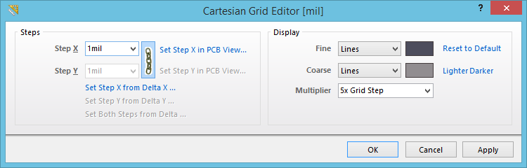
The Cartesian Grid Editor dialog
Summary
This dialog provides controls to view and modify properties for the default snap grid defined for the board. The default snap grid is used for object placement and movement in any area of the board. The Cartesian-type grid can be modified with respect to its step size and display.
Access
The dialog can be accessed from both the PCB Editor and PCB Library Editor:
- PCB Editor - click Home | Grids and Units |
 from the main menus. Alternatively, right-click in the workspace and use the Snap Grid » Grid Propereties command from the context menu.
 - PCB Library Editor - click Home | Grids and Units | Grids » Properties from the main menus. Alternatively, right-click in the workspace and use the Snap Grid » Grid Propereties command from the context menu.
Options/Controls
Steps
- Step X - use this field to define the distance between grid lines in the X plane. Type the required step size directly or select from a range of common sizes available in the associated drop-down list.
- Step Y - use this field to define the distance between grid lines in the Y plane. Type the required step size directly or select from a range of common sizes available in the associated drop-down list.
The following controls are also available, which allow you to define the X and/or Y step sizes directly from within the PCB workspace. In each case, you will be taken to the workspace to specify two 'calculating' locations, and the resulting step size will be calculated accordingly.
- Set Step X in PCB View - the resulting size is taken as the hypotenuse of the triangle formed by the chosen points in the workspace.
- Set Step Y in PCB View - the resulting size is taken as the hypotenuse of the triangle formed by the chosen points in the workspace.
- Set Step X from Delta X - the resulting size is taken using just the difference in the X coordinate.
- Set Step Y from Delta Y - the resulting size is taken using just the difference in the Y coordinate.
- Set Both Steps from Delta - the resulting sizes are taken using just the differences in the X and Y coordinates.
Display
- Fine - use the associated drop-down to define the markers used for the fine-level display of the grid in the workspace. Choose either
LinesorDots. The step size used for the markers is that defined in the Steps region. Click on the associated color swatch to access the standard Choose Color dialog, from where you can specify the color to be used for the fine-level display grid in the workspace. You can always reset the color back to its default using the Reset to Default link. - Coarse - use the associated drop-down to define the markers used for the coarse-level display of the grid in the workspace. Choose either
LinesorDots. The coarse-level display grid is the fine-level display grid with an increased step size in accordance with the entry selected in the Multiplier field. If you do not want to use the coarse-level display grid, choose the optionDo Not Draw. Click on the associated color swatch to access the standard Choose Color dialog, from where you can specify the color to be used for the coarse-level display grid in the workspace. You are free to choose a completely different color to that used for the fine-level display grid. Alternatively, you can quickly employ a lighter or darker shade of the color currently used for the fine-level display grid using the available Lighter or Darker links. You can reset the color back to its default using the Reset to Default link. - Multiplier - use this field to specify the required multiple of the grid's step size, either
2x Grid Step,5xGrid Step, or10x Grid Step.