Board Viewing Tools
Parent page: Commands

There are a number of tools available on the View tab of the Ribbon that you can use to control what is being viewed on the board, and how it is being viewed.
Summary
Aside from the standard View control type commands, such as zooming and panning, CircuitStudio includes other tools to help with working in a busy and dense design workspace. Use Single Layer Mode to quickly switch the display to only show the objects on the current layer, immediately reducing the visual clutter to a minimum. Filtering is available from a number of the PCB editor panels, fading all objects except those of interest.
CircuitStudio also supports displaying the board in both 2D and 3D, giving you a strong sense of what the assembled board will look like. More than just a tool for capturing an image for the marketing brochure, the PCB editor also supports real-time three-dimensional component clearance checking.
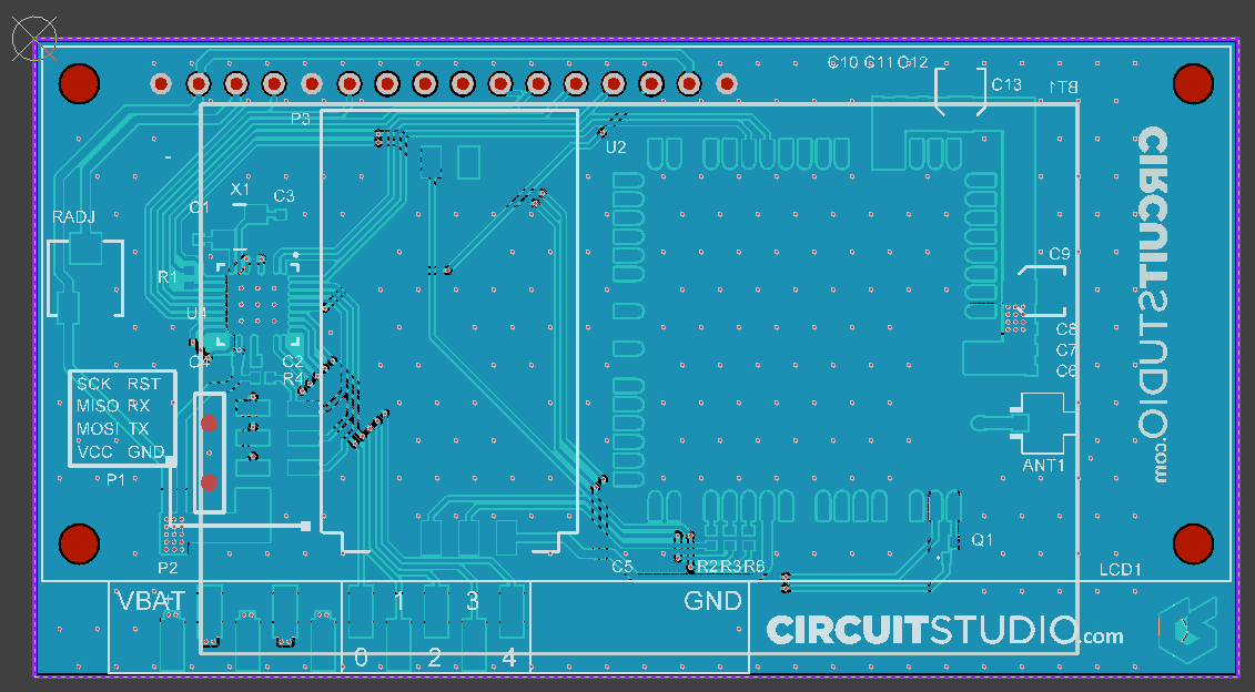
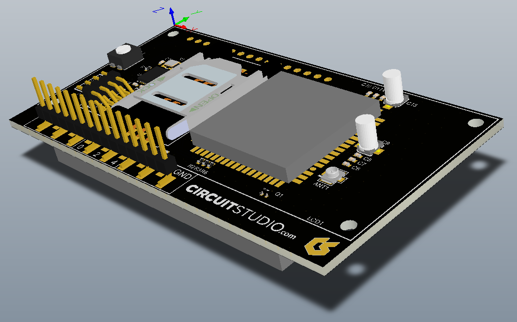
Using the 2 and 3 shortcuts, quickly switch from the traditional two-dimensional view to the highly realistic three-dimensional view.
Details
As well as using any of these commands on their own, zooming and panning shortcuts can also be used while another command, such as placing an object, is still being run.
| Command | Behavior |
|---|---|
| Zoom In | Zoom in closer to the PCB. Note that the zoom action occurs around the current cursor location, so clicking the Ribbon button does not always give an ideal result. Zoom In shortcuts include: - PgUp - Ctrl+Wheel Roll Up - Ctrl+Right-mouse click and hold, then move mouse up |
| Zoom Out | Zoom out from the PCB. Note that the zoom action occurs around the current cursor location, so clicking the Ribbon button does not always give an ideal result. Zoom Out shortcuts include: - PgDn - Ctrl+Wheel Roll Down - Ctrl+Right-mouse click & hold, then move mouse down |
| Zoom All | Zoom to show all objects in the workspace - shortcut Ctrl+PgDn. |
| Switch to 2D | Switch from 3D to 2D display mode - shortcut 2. In 2D mode, press the L shortcut to open the View Configurations dialog (View | View | Switch to 3D » View Configurations » View Configuration), where the visibility of layers and their colors are configured. Note that these settings are only available if you are currently viewing the board in 2D. |
| Switch to 3D | Switch from 2D to 3D display mode - shortcut 3. In 3D mode, press the L shortcut to open the View Configurations dialog (View | View | Switch to 2D » View Configurations » View Configuration), where the visibility of layers, their colors and opacity are configured. Note that these settings are only available if you are currently viewing the board in 3D. |
| View Configurations | View Configurations is the name given to the current configuration of visible layers, including their color and opacity (if in 3D mode). They are configured in the View Configurations dialog, which displays different options and controls for 2D and 3D display modes. |
| View Configurations - Altium Standard 2D | Switch to 2D display mode using the standard CircuitStudio layer visibility and color settings. |
| View Configurations - Altium 3D Black | Switch to 3D display mode using the standard CircuitStudio layer visibility, color settings and opacity for the 3D display mode. |
| Flip Board | Flip the board over (as if you were turning it over in your hand) to view the underside. |
| Single Layer Mode | Hide all layers except the currently active layer. Other layers are displayed in monochrome so that their contents can still be seen but do not interfere with your view of the current layer. |
| Mask Level # | Dim and Mask are display filter modes where everything other than the object(s) of interest are faded, leaving only the target object(s) at normal display strength. The Mask mode filters out all other workspace objects, only allowing the unfiltered object(s) to be edited. Use the slider to define how faded the masked objects are. |
| Dim Level # | Dim and Mask are display filter modes where everything other than the object(s) of interest are faded, leaving only the chosen object(s) at normal display strength. The Dim mode applies the filter but still allows all workspace objects to be edited. Use the slider to define how faded the dimmed objects are. |
| Clear # | Click the Clear button to remove a workspace filter (Mask or Dim) - shortcut Shift+C. |
| + / - (numeric keypad) | Step to the next (+) or previous (-) layer. |
| Ctrl+Shift+Wheel Roll | Step to the next layer (roll wheel forward one click) or previous layer (roll wheel backward one click). |
| Right+click and drag | Hold the right mouse button down to display the slider (panning) hand |
| Workspace Right-click | Right-click in the workspace to access the View menu, which includes a number of zoom-type commands, including: Fit Board, View Area, Zoom In, Zoom Out, Fit Selected and Filtered Objects. |