Variants
Contents
- Understanding Logical and Physical Components
- Types of Variations That Can be Performed
- Output Documents Affected by Variants
- Creating and Configuring a Variant
- Creating a New Variant
- Defining Component Variations
- Managing the Display of Data in the Variant Management Dialog
- Configuring the Display of Variants on the Schematic and PCB Drawings
- Resetting Variant Data
- Resetting a Varied Parameter
- Resetting Multiple Parameters for Multiple Components
- Working with Variant Parameters
- Working With Variants in the Schematic Editor
- Examining Varied Components on a Schematic
- Defining a Variation from the Schematic Sheet
- Working with Variants in the PCB Editor
- Viewing a Varied Component Comment
- Variant Errors
Parent page: Exploring CircuitStudio
The ability to create variations of the same base design is a real strength of CircuitStudio, and a tremendous productivity booster for designers. Using variants, you can define any number of variations of the base design and configure each component to be:
- Fitted
- Not fitted
- Fitted with modified component parameters, such as the component's value.
Variants that use any of these types of variations are all referred to as Assembly Variants, as they only impact on the assembly process - all variants share the same fabricated bare board. There is also support for variations to component overlay information on the PCB, for example, changing a components' comment. This type of variation requires two overlay screens to be produced, resulting in two different bare boards. This type of variant is referred to as a Fabrication Variant.
This article take a closer look at how to define and manage variants in CircuitStudio.
Understanding Logical and Physical Components
In CircuitStudio, there are two types of components: logical components and physical components. This distinction is important since it underlies some of the most powerful features in CircuitStudio. The components you place on the schematic sheet are logical components, each a conceptual entity that represents the actual component that is ultimately mounted on the assembled PCB.
While this one-to-one, logical-to-physical model works well for a simple design, it cannot support all of the design requirements needed by today's electronic product designer. CircuitStudio supports powerful concepts such as: multi-channel design, where a section of circuitry is stamped out as many times as you require; and variants, where a single design can be implemented with different components fitted to each variant of the board. Features such as this require the ability for one logical component to represent multiple physical components.
CircuitStudio delivers this one-to-many capability through its compiler technology. When you compile your logical design, each physical component is instantiated in memory, ready for transfer to the board design workspace.
Because there are situations where you still need access to the physical components at the schematic capture stage, the physical design is also made available in the schematic editor. The physical components are accessed via the extra tab(s) at the bottom of each schematic sheet. The left-most tab is the logical design you captured, the other tab(s), called the compiled tab(s), represent that chunk of physical design as it will be transferred to the PCB design workspace. Note that the schematic that is presented on the compiled tab cannot be graphically edited, for example, you cannot modify the wiring or move a component.
Types of Variations That Can be Performed
Before you can create a variant, you first create the original design, which is referred to as the base design. Working from the base design, you then go through a process of configuring the components to be: Fitted, Fitted with varied parameters, or Not Fitted.
- Fitted - this is the default state of a component. If it is Fitted, then it is not varied. When you create a new variant, all components default to Fitted. A component with a state of Fitted is represented in the Variant Management dialog as an empty cell.
- Fitted with Varied Parameter(s) - a component can have any of its parameters varied as part of the variant definition process. Modifying the value of a parameter is a local variation that only affects the output documentation. The original schematic, and the component whose parameter is being varied, are not modified in any way. In the image below, C13 has the Value parameter varied; this variation is shown by displaying the Value using a green, italic font.
- Not Fitted - if a component is set to Not Fitted, it still exists on the schematic and is transferred to the PCB, but it is removed from the appropriate output documentation, such as the BoM. You can configure how Not Fitted components are presented in the documentation, for example, they can be marked with a cross on the schematic and in PCB drawing outputs.
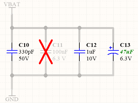
C10 and C12 are fitted, C11 is not fitted, and C13 is fitted with a parameter
value varied.
Output Documents Affected by Variants
Assembly variants affect all output documentation that includes details about the purchase or loading of components. This includes:
- Bill Of Materials
- Schematic Prints
- PCB Prints
- PCB 3D Prints
- Assembly Drawings
- Pick and Place files
Fabrication variants also affect the following outputs:
- Gerber overlay layers
- ODB++ overlay layers
Creating and Configuring a Variant
Variants are created and configured in the Variant Management dialog (click Project | Project Actions | ![]() from the main menus of any document in the project). The dialog has two main regions:
from the main menus of any document in the project). The dialog has two main regions:
- The upper region, titled Project Components, lists all of the components in the base design;
- The lower region, titled Parameter Variations, details all of the parameters of the component(s) currently selected in the upper region.
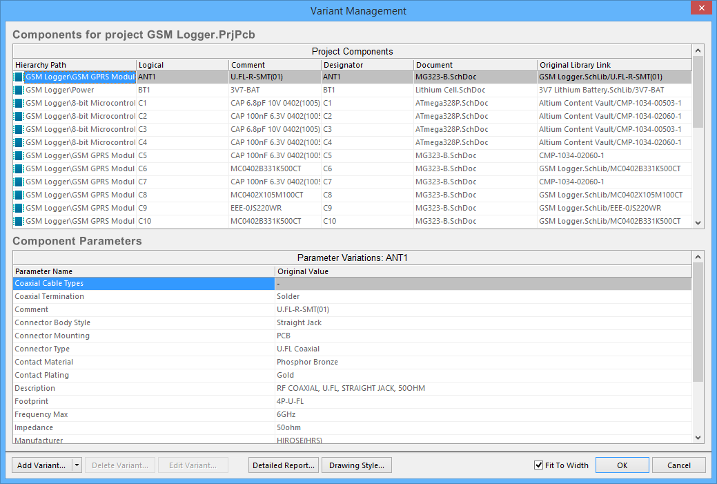
Variants are created and configured in the Variant Management dialog.
Creating a New Variant
Click the Add Variant button in the Variant Management dialog to create a new variant of the base design. The Edit Project Variant dialog will open. Use this dialog to give the variant a meaningful name and specify any required variant-level parametric data.
An additional column will appear on the right side of the Variant Management dialog, with the just-added Variant description as the column title. All the cells will be empty; an empty cell indicates that this component is Fitted and is unchanged from the base design. You are now ready to configure the components for the new variant.
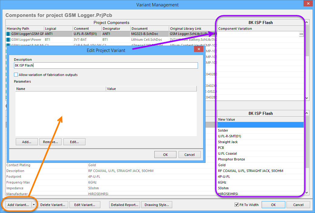
Example of a newly-added variant
Defining Component Variations
Once the variant has been created, you are ready to configure the state of each component. This can be done by clicking the Component Variation cell in the variant column to reveal the ![]() button, or by right-clicking to access the context menu commands. When the
button, or by right-clicking to access the context menu commands. When the ![]() button is clicked, the Edit Component Variation dialog will open, presenting you with two choices:
button is clicked, the Edit Component Variation dialog will open, presenting you with two choices:
- Fitted - the original component as used in the base design is also fitted/used in this variant of that design. For a newly-added variant, all components are fitted by default. The cell for a fitted component is empty. Note that individual parameters can also be varied for a fitted component - type in the new parameter value. Varied parameters are shown in bold.
- Not Fitted - the original component as used in the base design is not fitted/used in this variant of that design. For a Not Fitted component, the cell displays the text Not Fitted.
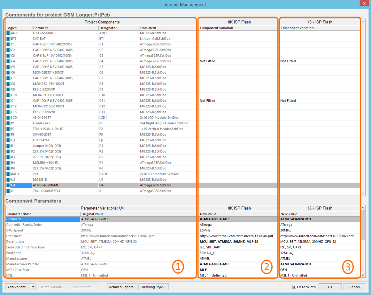
Example defined variants. Region 1 in the image details the components in the base design, region 2 details the components in the variant called 8K ISP Flash, region 3 details the components in the variant called 16K ISP Flash. Note the bold parameters, indicating that these parameters have different values from the base design.
Managing the Display of Data in the Variant Management Dialog
The Variant Management dialog includes various features to help control the amount of data displayed:
- To remove columns that you are not interested in, right-click in the upper region of the dialog and toggle the visibility of any column in the Columns sub-menu.
- To display only those components being varied, right-click in the upper region of the dialog then select Only Show Varied Components from the menu.
- After selecting the Only Show Varied Components mode, right-click again and configure the Filter options as required. In the image below, the Filter has been configured to only display components that are Not Fitted.
- To change the order the variants are listed, click and hold on the column heading, then drag that column to a new location. Use this in combination with the Fit to Width checkbox to position and size the variant of interest in your preferred working location.
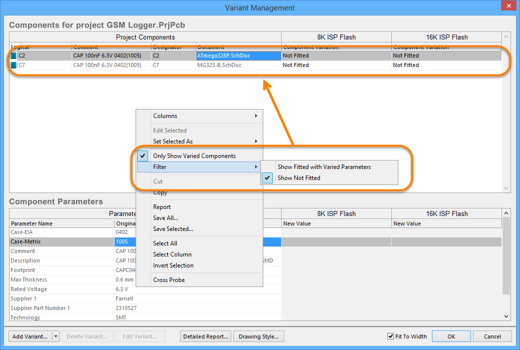
The Variant Management dialog with columns hidden and a filter applied to only show components that are Not Fitted.
Configuring the Display of Variants on the Schematic and PCB Drawings
Dialog page: Variant Options
As the designer, you have control over the way in which varied components are presented on the schematic sheets (which then flows through to printed or PDF outputs), and in PCB drawing type outputs, such as assembly drawings. These are configured in the Variant Options dialog, as shown below. To access the dialog, click the Drawing Style button at the bottom of the Variant Management dialog.
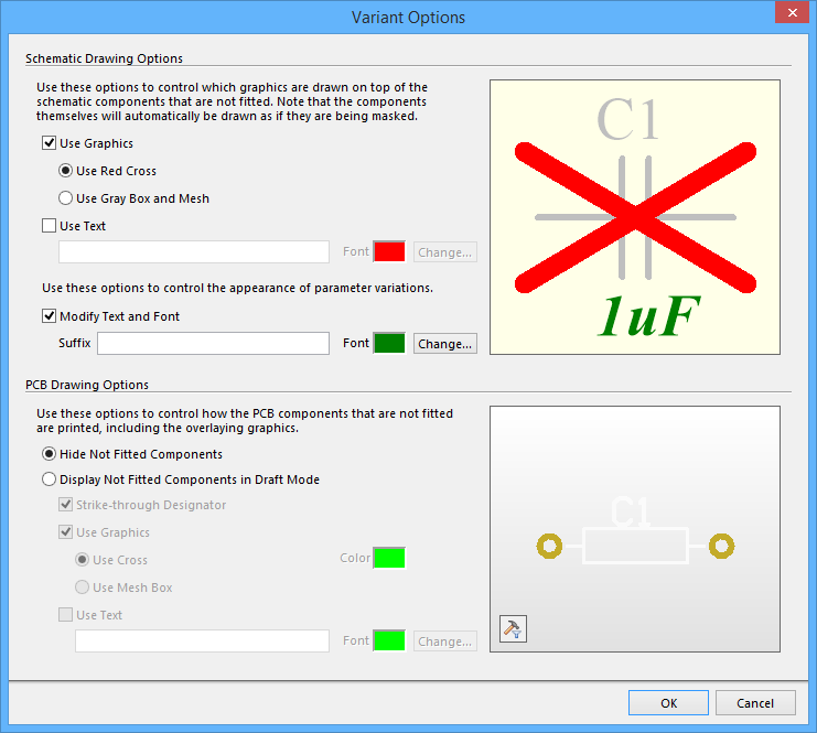
Configure how the not fitted components for defined variants are presented on the schematic and in PCB drawing outputs, in the Variant Options dialog.
Resetting Variant Data
When you configure variations in the Variant Management dialog, the settings are saved in the project file. This includes the Not Fitted state and local parameter variations to a Fitted component. The Variant Management dialog includes commands for resetting parameters, back to the standard values used in the base design.
Resetting a Varied Parameter
Parameters modified locally in the Variant Management dialog can be restored to their original value by right-clicking on the modified parameter in the Variant Parameter list (shown in bold), and selecting Reset Selected from the menu, as shown below. Note that you can multi-select and reset the value of multiple parameters in a single action, or alternatively, Reset All parameters for that component.
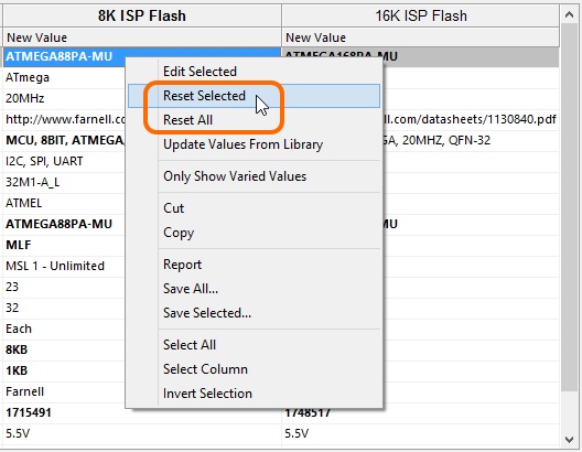
Modified parameters can have their value(s) restored using the Reset Selected or
Reset All commands.
Resetting Multiple Parameters for Multiple Components
The Variant Management dialog supports multi-select, which means you can select many or all components across many or all variants in the upper region of the dialog, then perform parameter update actions on one or more parameters for one or more components in one or more variants.
As an example, you might want to reset the manually varied parameters for all components in all variants.
To do this:
- Use the Only Show Varied Components right-click menu option, in combination with the right-click Filter options to only Show Fitted with Varied Parameters. The upper region of the dialog should now display only those components that have manually varied parameters.
- Right-click in the upper region of the dialog again then choose Select All from the context menu. All components currently displayed in the upper part of the dialog will be selected.
- Now right-click in the lower region of the dialog then choose Select All from that context menu. All parameters for all components will now be selected. Note that you could have chosen the Select Column command instead to only apply the Reset action to the components in a specific Variant.
- Right-click again in the lower region of the dialog then choose Reset Selected from the context menu.
Working with Variant Parameters
CircuitStudio supports parameters at various levels of the project. For example, you can add document-level parameters to each schematic sheet in the Document Options dialog. You can also add project-level parameters to the project on the Parameters tab of the Project Options dialog (Project | Content | Project Options). Parameters can also be added to a variant in the Edit Project Variant dialog.
Parameters have a hierarchy, which means you can create a parameter with the same name at different levels of the project, each having different values. CircuitStudio resolves this in the following way:
- Variant (highest priority)
- Schematic document
- Project
This means that the parameter value defined in the schematic document overrides the value defined in the project options, and the value defined in the variant overrides the value defined in the schematic document. Note that schematic-level parameters are not available on the PCB or in the BoM. For these types of outputs, you should use project or variant parameters.
In the images below, a Parameter called ProjectTitle has been defined for the project, and also for each variant. The animation shows the behavior on the PCB as the Current Variant field on the ribbon menus is used to show the base design, then each variant.
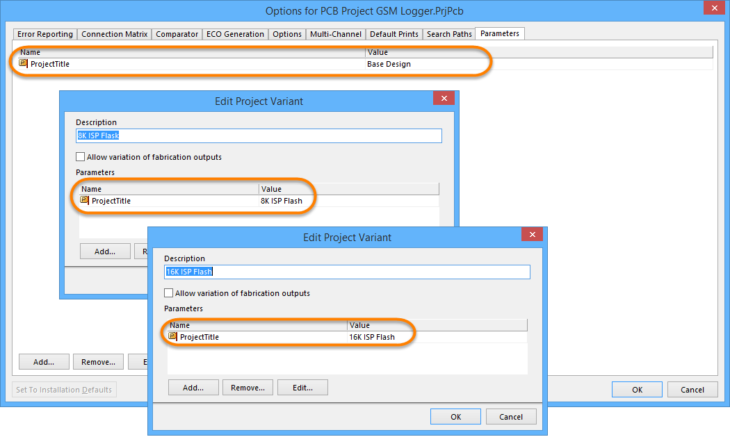

The special string .ProjectTitle was placed on the PCB overlay, which is automatically
linked to parameters of the same name. Note how the value changes as the Variant is changed.
Working With Variants in the Schematic Editor
It is important during design capture that you have complete visibility of the component variations used in each variant. To support this, the schematic editor includes a number of features as described below.
Examining Varied Components on a Schematic
To examine variant detail on a schematic you:
- Compile the project if it is not already compiled.
- Select the compiled tab down the bottom of the schematic sheet.
- Select the required variant in the Project | Project Actions | Current Variant dropdown.
- Components varied on this sheet will then be displayed, as configured in the Variant Options dialog.

Select the compiled sheet and the Variant (orange highlights) to view the components varied on the schematic sheet.
Defining a Variation from the Schematic Sheet
It is often easier to work directly from the component(s) placed on the schematic sheet rather than scrolling up and down through a list of components in a dialog. Select the component(s) on the sheet then right-click and select Part Actions » Variants from the menu, as shown below.
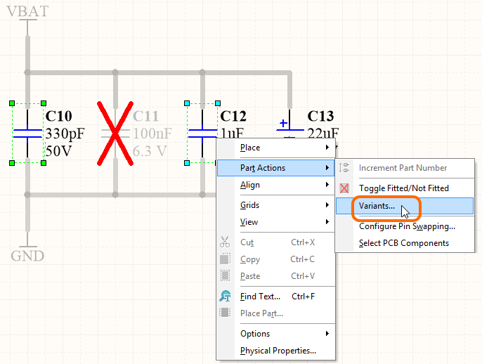
Two capacitors have been selected on the schematic. Use the right-click command to configure just those components in the Variant Management dialog.
The Variant Management dialog will open, displaying only the selected components. Perform the required variations then click OK to apply them to the design.
Working with Variants in the PCB Editor
In the PCB editor, all of the component footprints for all variants are always shown. This is necessary because all footprints, for all assembly variants, must be fabricated as part of the bare board. It is the loading of components during the assembly process that then determines which variant is being built.
Because all footprints are always visible on the PCB, it can be difficult to know which components belong to which variant. The PCB editor provides the Project | Project Actions | Current Variant drop-down, which can be used to switch between variants. However, the only visible clue to tell if a particular component is fitted or not fitted in that variant is if the component includes a 3D Body; that body will appear/disappear to indicate when the component is fitted or not fitted. This fitted/not fitted behavior can be seen much more easily when the PCB is in 3D Layout Mode, as demonstrated in the animated image below.
Viewing a Varied Component Comment
CircuitStudio allows fabrication outputs to be driven by variants. More specifically, this allows you to specify a change to a component's Comment parameter, and that change will be passed to the fabrication output – the silkscreen layer of the generated Gerber or ODB++ output. The PCB Editor supports the visual display of such a change; the Comment field will reflect the value assigned for the currently chosen variant directly in the workspace.
With the variants defined, locate a component of interest in the PCB workspace – whose Comment parameter is varied – and switch the current variant from the Project | Project Actions | Current Variant drop-down field. The displayed value for the comment will change in accordance with what has been defined for that current variant.

Viewing a varied comment for a component in 2D and 3D.
Variant Errors
Variant settings are stored in the project file (*.PrjPcb). When the Variant Management dialog is opened, this data is read and analyzed, then loaded into the Variant Management dialog. If there are issues detected during data loading, such as mismatches between component designators or component UIDs, an Information dialog will open outlining the problem, as shown in the image below.
Component UID mismatches are automatically resolved by closing the dialog and saving the project to retain these corrections. Duplicate designators must be resolved at the schematic level. Recompile the project and check the Messages panel for warning/error details to resolve these.
Resolve designator and UID mismatches before continuing with the design process.